High-efficiency laser pumping source device
A laser pumping and source device technology, applied in the direction of laser monitoring devices, lasers, laser components, etc., can solve the problems of burning out power tubes, increasing electrical loss of power control modules, and decreasing overall efficiency
- Summary
- Abstract
- Description
- Claims
- Application Information
AI Technical Summary
Problems solved by technology
Method used
Image
Examples
Embodiment 1
[0041] Embodiment 1 Overall structure of the system
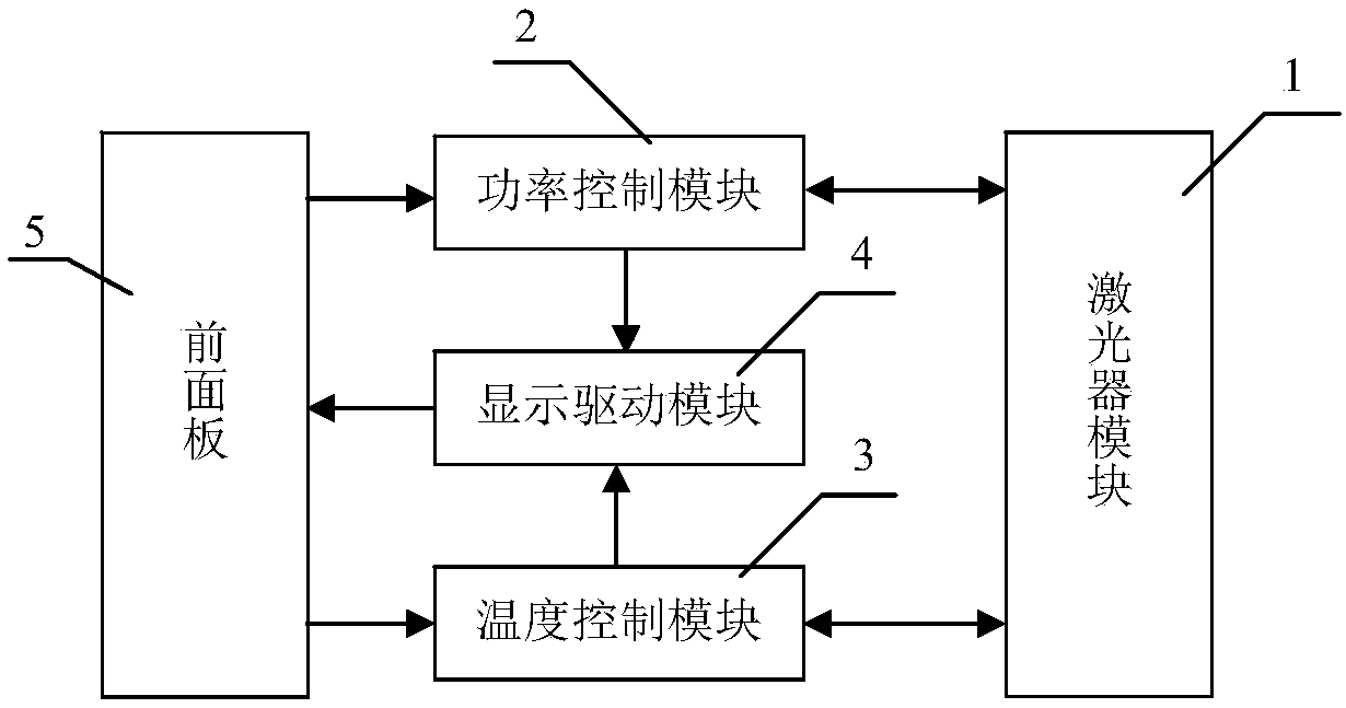
[0042] Such as figure 1 As shown, the system structure includes a laser module 1, a power control module 2, a temperature control module 3, a display driver module 4, and a front panel 5. The power control module 2 provides driving current to the laser module 1, and the temperature control module 3 controls the laser module 1. The working temperature is to make it work in a constant temperature state, and the display drive module 4 collects the main parameters of the system and converts them into signals suitable for meter display. The front panel 5 is used to operate the pump source device of the present invention.
Embodiment 2
[0043] Embodiment 2 The structure of the power control module 2 of the present invention
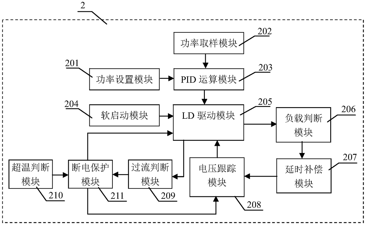
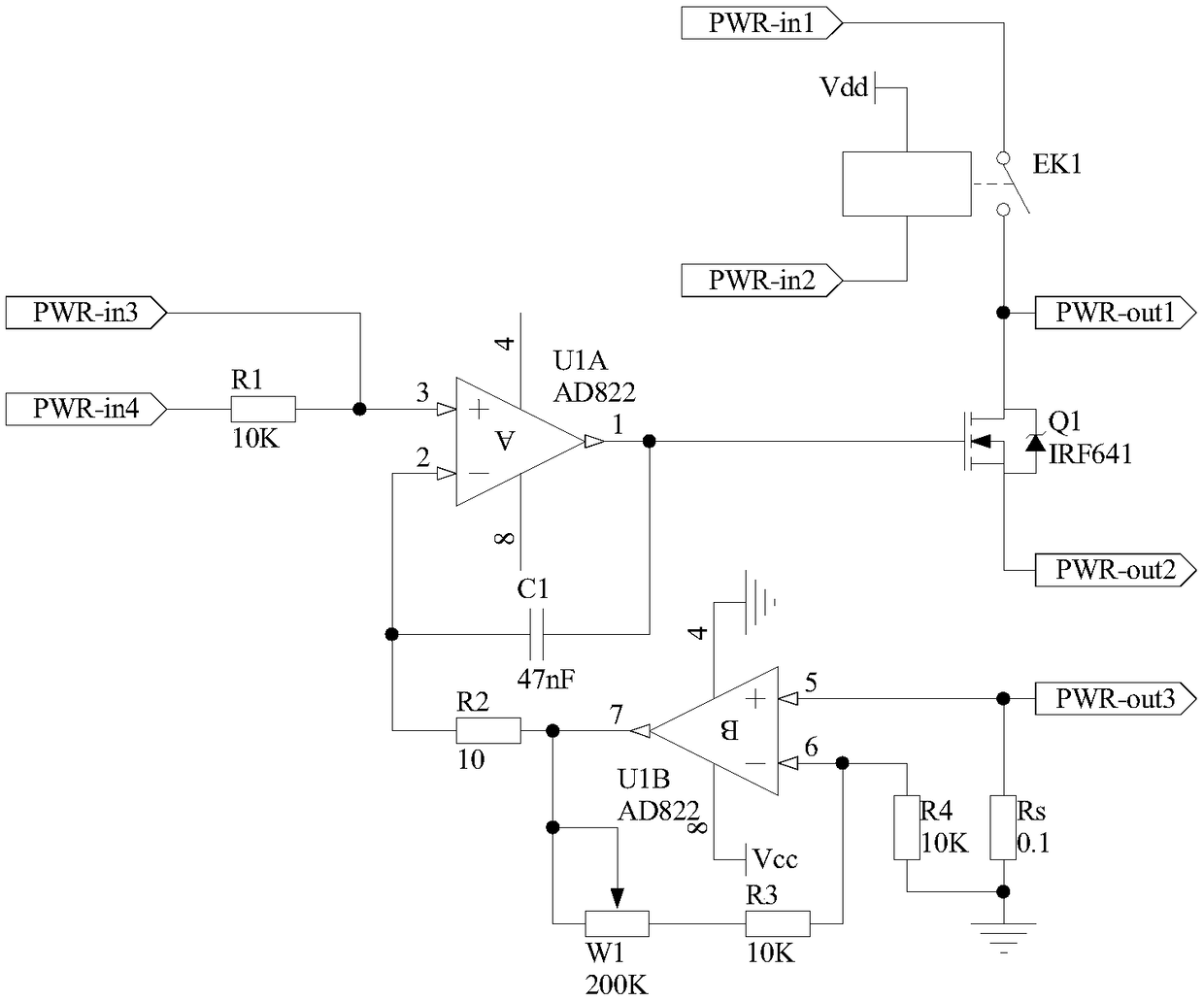
[0044] The structure of the power control module 2 is as figure 2 As shown, it includes a power setting module 201, a power sampling module 202, a PID calculation module 203, a soft start module 204, an LD driver module 205, a load judging module 206, a delay compensation module 207, a voltage tracking module 208, and an overcurrent judging module 209 , an over-temperature judging module 210 and a power-off protection module 211. The required power is set by the power setting module 201, and the power sampling module 202 samples the output optical power through the photodiode (PD) integrated in the laser module 1 and converts it into a voltage, and then performs PID calculation with the voltage set by the power setting module 201 In the module 203, the difference is calculated and the PID operation is performed. The result of the operation is output to the LD drive module 205 and contro...
Embodiment 3
[0048] Embodiment 3 The load judging module of the present invention
[0049] The structure of the load judging module 206 of the present invention is as follows Figure 4 As shown: the non-inverting input terminal of the operational amplifier U2A is used as the first input terminal of the load judgment module 206, which is denoted as port Vjdg-in1, and is connected to the port PWR-out1 of the LD driver module 205, and the inverting input terminal of the operational amplifier U2A is connected to the The output terminal of operational amplifier U2A is connected to one end of resistor R5, the other end of resistor R5 is connected to one end of resistor R6 and the same-inverting input terminal of operational amplifier U3A, the other end of resistor R6 is grounded, and the output terminal of operational amplifier U3A is connected to the in-phase input terminal of operational amplifier U3A. One end is connected to one end of the resistor R9, the other end of the resistor R8 is conn...
PUM
 Abstract
Description
Claims
Application Information
 - R&D
- Intellectual Property
- Life Sciences
- Materials
- Tech Scout
- Unparalleled Data Quality
- Higher Quality Content
- 60% Fewer Hallucinations
Browse by: Latest US Patents, China's latest patents, Technical Efficacy Thesaurus, Application Domain, Technology Topic, Popular Technical Reports.
© 2025 PatSnap. All rights reserved.Legal|Privacy policy|Modern Slavery Act Transparency Statement|Sitemap|About US| Contact US: help@patsnap.com


