
An all-fiber chirped pulse velocity interferometer

A chirped pulse, all-fiber technology, applied in the field of laser testing equipment, can solve the problems of large system volume, strong oscillation of speed signal, high cost, and achieve the effect of simple and direct process, reduced signal oscillation, and easy debugging.

Active Publication Date: 2022-02-08
LASER FUSION RES CENT CHINA ACAD OF ENG PHYSICS
View PDF6 Cites 0 Cited by
  • Summary
  • Abstract
  • Description
  • Claims
  • Application Information

AI Technical Summary

Problems solved by technology

For the velocity measurement of high-speed moving bodies, the commonly used diagnostic equipment includes the velocity interferometer on any reflective surface (VISAR), the all-fiber laser displacement interferometer (DISAR) and the laser frequency domain interferometer. Among them, VISAR uses expensive streak cameras or oscilloscopes. As a recording device, limited by the time resolution capability of these devices and other factors, it is difficult for VISAR to achieve a time resolution measurement of less than 10 ps; when DISAR is used as a displacement interferometer to measure speed signals, it is difficult for low speeds with very high acceleration Signal measurement is powerless. In addition, considering the data processing process and oscilloscope recording equipment, the speed measurement time resolution of DISAR is usually not lower than 100ps; the laser frequency domain interferometer has unique advantages in measuring high-speed signals. It uses ordinary As a recording device, a spectrometer can achieve picosecond or even sub-picosecond time-resolved measurement. Based on laser frequency domain interferometry technology, the Laser Fusion Research Center of the Chinese Academy of Engineering Physics has applied for two Chinese invention patents: a chirp Pulse velocity interferometer (Patent No. ZL201310706464.X) and an all-fiber frequency domain interferometer (Patent No. ZL201420658771.5), however, the former is composed of discrete optical components, the system is large in size, high in cost, and the debugging process is complicated, while the latter The recorded data is obtained by the interference of two separately transmitted reference light and signal light, which will reduce the signal-to-noise ratio of the data, and the displacement differential operation in the data processing process makes the obtained velocity signal have a strong oscillation, thus Detrimental effect on the accurate interpretation of the speed signal

Method used


Image

  • An all-fiber chirped pulse velocity interferometer

Examples


Embodiment Construction

[0023] The present invention will be further described below with reference to the accompanying drawings and examples, and the modes of the present invention include but are not limited to the following examples.

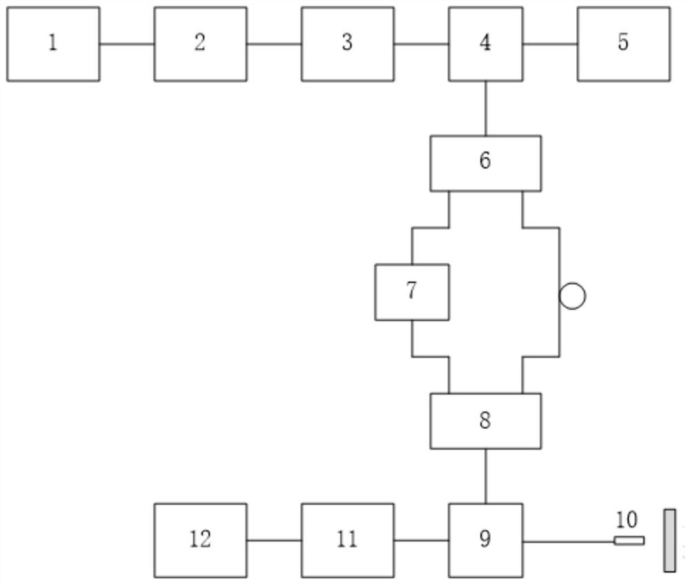
[0024] This embodiment provides an all-fiber chirped pulse velocity interferometer with a simple structure and easy debugging, see figure 1 , the velocity interferometer includes the following fiber components: supercontinuum fiber laser 1, filter 2, fiber isolator 3, circulator I4, chirped fiber grating 5, fiber beam splitter 6, fiber retarder 7, fiber combiner 8, circulator II 9, fiber probe 10, fiber amplifier 11, fiber spectrometer 12; among them, the supercontinuous fiber laser 1 is a pulsed laser, and the output spectral range of the pulsed laser includes 1520-1580nm, and is distributed in the spectral range of 1520-1580nm levelling; in addition, pulsed lasers can operate in single-pulse output mode. Filter 2 is a band-pass filter with a pass-band range of 15...


PUM


Abstract

The invention discloses an all-fiber chirped pulse velocity interferometer, comprising a supercontinuous fiber laser, a filter, a fiber isolator, a circulator I, a chirped fiber grating, a fiber beam splitter, a fiber delayer, and a fiber combiner , circulator II, fiber optic probe, fiber amplifier, fiber optic spectrometer; the supercontinuum fiber laser, filter, fiber isolator and circulator I are connected in sequence, and the circulator I is connected with a chirped fiber grating and a fiber beam splitter, and the optical fiber The beam splitter is respectively connected to the fiber beam combiner through the fiber delayer and the fiber jumper, and the circulator II is respectively connected to the fiber beam combiner, the fiber probe and the fiber amplifier, and the fiber amplifier is connected to the fiber spectrometer. The interferometer has a simple structure and is easy to debug. Using this interferometer to measure the speed of a high-speed moving body, the time resolution can reach the level of picoseconds, and its optical path design is conducive to obtaining data with a high signal-to-noise ratio, and the data can be directly reconstructed Speed ​​signal, improve speed measurement accuracy.

Description

technical field [0001] The invention relates to a laser testing device, in particular to an all-fiber chirped pulse velocity interferometer. Background technique [0002] The research on the dynamic response characteristics of materials under the action of strong shock waves is one of the frontier physics topics. It is an important research content to load metal materials with high-power pulsed lasers and accurately measure their free-surface velocity profiles with high time resolution. For the velocity measurement of high-speed moving objects, commonly used diagnostic equipments include velocity interferometer with arbitrary reflective surface (VISAR), all-fiber laser displacement interferometer (DISAR) and laser frequency domain interferometer, among which VISAR uses an expensive fringe camera or oscilloscope As a recording device, limited by the time resolution capability of these devices and other factors, it is difficult for VISAR to achieve time-resolved measurements b...

Claims


Application Information

Patent Timeline
Patent Type & Authority Patents(China)
IPC IPC(8): G01P3/36
CPCG01P3/36
Inventor 范伟董克攻朱斌李纲闫永宏杨月卢峰于明海谭放张天奎吴玉迟谷渝秋
Owner LASER FUSION RES CENT CHINA ACAD OF ENG PHYSICS
Learn More