Novel catalytic desulfurization and denitration apparatus and technology aiming at coke oven flue gas

A technology for desulfurization, denitration and flue gas, which is applied in the field of coke oven flue gas purification, can solve the problems of high energy consumption, low flue gas temperature, and can not meet the temperature requirements of alum-based catalysts, and achieves low energy consumption, simple regeneration process, Small footprint effect

Inactive Publication Date: 2019-05-03
XIAN MEIZHILV INFORMATION TECH CO LTD
0 Cites 0 Cited by

AI-Extracted Technical Summary

Problems solved by technology

[0011] b) If the SCR is arranged after desulfurization, the dust and SO 2 The concentrations are all low, but the flue gas temperature is low, which cannot meet the temperature requirements of alum-ba...

Abstract

A novel catalytic desulfurization and denitration apparatus and technology aiming at coke oven flue gas, relating to the field of coke oven flue gas purification. In the desulfurization, by using water, oxygen, SO2 and heat in flue gas, sulfuric acid in certain concentration is produced; in the denitration, by means of the denitration principle of NH3-SCR, a nano multi-metal catalyst is used as adenitration catalyst with assistance of an ammonia removal catalyst, thus achieving integration of denitration and ammonia removal. The key of the technology is the catalysts: in the desulfurization,a desulfurizer prepared by supporting a certain active component on a supporter, wherein the desulfurizer has catalytic effect on the SO2 oxidization to produce acid process; in the denitration, by using the nano multi-metal catalyst as the denitration catalyst, reaction temperature zone is controlled at 80-140 DEG C, so that the catalyst is a real low-temperature catalyst. The whole technology issimple in process and low in energy consumption.

Application Domain

Dispersed particle separation

Technology Topic

ChemistryFlue gas +12

Image

  • Novel catalytic desulfurization and denitration apparatus and technology aiming at coke oven flue gas
  • Novel catalytic desulfurization and denitration apparatus and technology aiming at coke oven flue gas
  • Novel catalytic desulfurization and denitration apparatus and technology aiming at coke oven flue gas

Examples

  • Experimental program(1)

Example Embodiment

[0055] The present invention will be further described below in conjunction with the drawings and embodiments.
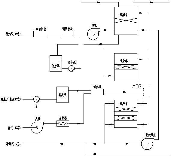
[0056] Such as Figure 1-Figure 3 As shown, a new type of catalytic desulfurization and denitrification device for coke oven flue gas, the catalytic desulfurization device is equipped behind the discharge port of coke oven flue gas, the catalytic desulfurization device includes a coke oven flue gas discharge port through Waste heat recovery device connected by pipeline;
[0057] The waste heat recovery device is also connected to the flue gas conditioning system through a pipe, and the flue gas conditioning system is also connected to the flue gas inlet 11 of the desulfurization tower through a pipe provided with a blower;
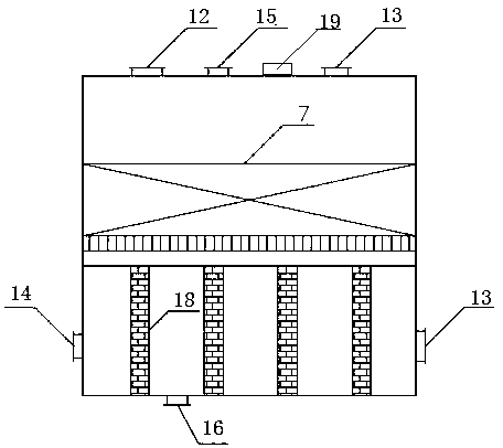
[0058] The sulfuric acid outlet 16 of the desulfurization tower is connected to the regeneration tank through a pipeline, and the regeneration tank is also connected to the spray inlet 15 of the desulfurization tower through a pipeline provided with a regeneration pump;
[0059] The flue gas outlet 12 of the desulfurization tower and the air outlet 13 of the desulfurization tower are each connected to a chimney through a pipe, and the chimney is also connected to the air inlet 14 of the desulfurization tower through a pipe provided with a blower;
[0060] The oxidation tower is connected to the exhaust port 19 of the desulfurization tower through a pipeline;
[0061] The oxidation tower is also connected to the ammonia injection grid AIG through a pipeline, and the ammonia injection grid AIG is respectively connected to the mixer, the first flue gas inlet 1 of the denitrification tower, and the second flue gas inlet 2 of the denitrification tower through the pipeline. through;
[0062] The mixer is also communicated with the evaporator and the heater through pipes;
[0063] The evaporator is also communicated with a pipe provided with a pump, and the heater is also communicated with a pipe provided with a fan.
[0064] The waste heat recovery device is used to allow the coke oven flue gas to pass through the waste heat recovery device to recover the waste heat of the coke oven flue gas and reduce the temperature of the flue gas;
[0065] The flue gas conditioning system is used to adjust the temperature of the coke oven flue gas and the humidity of the coke oven flue gas, so that the temperature of the coke oven flue gas and the humidity of the coke oven flue gas meet the requirements of the desulfurization catalyst in the desulfurization tower;
[0066] The desulfurization tower is used to allow the coke oven flue gas entering the desulfurization tower to pass through the desulfurization catalyst layer, so that the H in the coke oven flue gas 2 O, SO 2 And O 2 Be adsorbed, and the clean flue gas thus obtained can be discharged;
[0067] The desulfurization catalyst layer 7 in the desulfurization tower is used to adsorb H on the desulfurization catalyst. 2 O, SO 2 And O 2 , Under the action of desulfurization catalyst, SO 2 And O 2 Reaction to form SO 3 , SO 3 With H 2 O combined to generate H 2 SO 4;
[0068] The desulfurization catalyst reaches saturation after working for a period of time, and the H stored on the desulfurization catalyst is washed with water. 2 SO 4 Take it out to form diluted sulfuric acid, and at the same time it is washed with water to regenerate the desulfurization catalyst;
[0069] Introduce clean flue gas into the desulfurization tower through a reverse blower, and dry the desulfurization catalyst;
[0070] The oxidation tower is used to oxidize the flue gas discharged from the exhaust port of the dry denitration device through the oxidation catalyst in the oxidation tower to oxidize part of the NO in the flue gas to NO 2 To make NO/NO 2 Ratio reaches a certain value;
[0071] The evaporator is used to evaporate liquid ammonia or ammonia water into a gaseous state through the evaporator, and then mix it with air to form a mixture. The ammonia gas is diluted to less than 5%, and the diluted ammonia gas passes through the ammonia injection grill AIG and then mixes with the smoke. The gas is uniformly mixed into a flue gas mixture in the pipeline leading to the denitrification tower;
[0072] The denitration tower is used to allow the flue gas mixture entering the denitration tower to pass through the denitration catalyst layer 5, so that the NH in the flue gas mixture 3 , O 2 And NOx, under the action of denitration catalyst, react to form N 2 And H 2 0;
[0073] The denitration catalyst in the denitration tower can also be used to adsorb unreacted NH 3.
[0074] The oxidation tower is provided with an oxidant layer with oxidant.
[0075] The denitration tower includes a second tower body, in which a denitration catalyst layer 5 with a denitration catalyst is arranged, and the denitration catalyst layer 5 has two denitration catalyst layers in total, and the two denitration catalyst layers are The order from top to bottom is the upper catalyst layer and the lower catalyst layer;
[0076] A first flue gas inlet 1 and a second flue gas inlet 2 communicating with the inside of the second tower body are sequentially arranged on one side wall of the second tower body from top to bottom, and the first flue gas The inlet 1 and the second flue gas inlet 2 are respectively located above the denitration catalyst layer 5 and below the denitration catalyst layer 5;
[0077] The other side wall of the second tower body is sequentially provided with a first flue gas outlet 3 and a second flue gas outlet 4 communicating with the inside of the second tower body in order from top to bottom, and the first flue gas The outlet 3 and the second flue gas outlet 4 are respectively located above the denitration catalyst layer 5 and below the denitration catalyst layer 5;
[0078] The first flue gas outlet 3 and the second flue gas outlet 4 are in communication with the chimney.
[0079] The desulfurization tower includes a first tower body in which a desulfurization catalyst layer 17 with a desulfurization catalyst is arranged, and the bottom of the first tower body is provided with sulfuric acid communicating with the inside of the first tower body. Exit 16;
[0080] A flue gas inlet 11 communicating with the inside of the first tower body is provided on one side wall of the first tower body;
[0081] The other side wall of the first tower body is provided with an air inlet 14 communicating with the inside of the first tower body;
[0082] The top wall of the first tower body is provided with a flue gas outlet 12, an exhaust port 19, an air outlet 13 and a spray inlet 15 which are connected to the inside of the first tower body.
[0083] The anti-corrosion column 18 in the first tower body supports the desulfurization catalyst layer 7 in the first tower body.
[0084] The process of the novel catalytic desulfurization and denitration device for coke oven flue gas is specifically as follows:
[0085] Step 1: The coke oven flue gas passes through the waste heat recovery device to recover the waste heat of the coke oven flue gas. After the temperature of the coke oven flue gas is reduced, the coke oven flue gas continues to pass through the flue gas conditioning system to adjust the coke oven The temperature of the flue gas and the humidity of the coke oven flue gas, and then the coke oven flue gas enters the desulfurization tower under the action of a blower;
[0086] Step 2: After the coke oven flue gas enters the first tower body from the flue gas inlet 1 of the desulfurization tower, it adsorbs H in the coke oven flue gas through the desulfurization catalyst in the desulfurization catalyst layer 7 2 O, SO 2 And O 2 , And then the clean flue gas flows out from the flue gas outlet 2 until the chimney is discharged;
[0087] Step 3: The H on the surface of the desulfurization catalyst adsorbed in the desulfurization catalyst layer 7 2 O, SO 2 And O 2 , The catalytic reaction generates H 2 SO 4 In this way, the aqueous solution is drawn from the regeneration tank through the regeneration pump, and sent to the spray inlet 5 on the top wall of the first tower body of the desulfurization tower, so as to flush the desulfurization catalyst and remove the H on the desulfurization catalyst. 2 SO 4 Transfer from the sulfuric acid outlet 6 to the regeneration tank until the concentration of sulfuric acid in the regeneration tank reaches the set value, which is used to produce acid or sulfate;
[0088] Step 4: After flushing the desulfurization catalyst, the desulfurization catalyst resumes its activity, so that clean flue gas is extracted from the air inlet 4 through the reverse blower, and the moisture on the surface of the desulfurization catalyst is sent to the chimney from the air outlet 3;
[0089] Step 5: Liquid ammonia or ammonia water is pumped to the evaporator, evaporates into gaseous state, and then mixed with the air delivered by the fan in the mixer, and the ammonia gas is diluted to less than 5%;
[0090] Step 6: The flue gas discharged from the exhaust port enters the oxidation tower, passes through the oxidation catalyst layer, part of NO and O 2 Under the catalytic action of the oxidation catalyst in the oxidation catalyst layer, the reaction produces NO 2;
[0091] Step 7: After the diluted ammonia gas passes through the ammonia injection grid AIG, it is evenly mixed with flue gas in the pipeline leading to the denitrification tower to form a flue gas mixture, and then the flue gas mixture enters the denitrification tower, and the flue gas mixture first The second flue gas inlet 2 enters the second tower body, passes through the lower catalyst layer, NOx and NH 3 Under the action of the catalyst, the reaction produces N 2 And H 2 0, the flue gas mixture after the reaction goes up, the NH escaped in the flue gas mixture 3 Adsorbed by the upper catalyst layer, the flue gas is discharged from the first flue gas outlet 3 to the chimney; wait for the upper catalyst layer to adsorb NH 3 After saturation, switch the flue gas inlet to allow the flue gas mixture to enter the second tower from the first flue gas inlet 1, and pass through the upper catalyst layer. Under the action of the NOx and the denitration catalyst, the NH adsorbed on the surface of the denitration catalyst 3 Reaction to generate N 2 And H 2 0, the flue gas mixture after reaction goes down, NH escaped in the flue gas mixture 3 Adsorbed by the lower catalyst layer, the flue gas is discharged from the second flue gas outlet 4 to the chimney.
[0092] The beneficial effects of the present invention are:
[0093] The desulfurization catalyst used in the desulfurization of the present invention does not need to add any other desulfurization agent, and the operating cost is low; the desulfurization catalyst can be regenerated, the regeneration process is simple, no heating is required, and it can be washed with water, and the regeneration process produces diluted sulfuric acid. Economic value, no other waste water is produced; the temperature of the coke oven flue gas remains basically unchanged after the desulfurization and denitrification device, and can be directly discharged; the reaction temperature of the denitrification catalyst is low, and the reaction temperature range is 80~140℃, which is a true low-temperature catalyst; The NOx in the gas is catalytically reduced to N which does not pollute the environment 2 And H 2 0; The denitration catalyst has a long chemical life, up to 24000h; the denitration catalyst has a high denitration efficiency, which can reach more than 85%. The process flow is simple, the equipment is small, the area is small, the construction cost is low; the electric equipment is small, and the energy consumption is low.
[0094] The present invention has been described above in the form of illustration with the accompanying drawings. Those skilled in the art should understand that the present disclosure is not limited to the embodiments described above, and various changes and changes can be made without departing from the scope of the present invention. And replace.

PUM

no PUM

Description & Claims & Application Information

We can also present the details of the Description, Claims and Application information to help users get a comprehensive understanding of the technical details of the patent, such as background art, summary of invention, brief description of drawings, description of embodiments, and other original content. On the other hand, users can also determine the specific scope of protection of the technology through the list of claims; as well as understand the changes in the life cycle of the technology with the presentation of the patent timeline. Login to view more.

Similar technology patents

Liquid nitrogen cooling cryogenic device and implementation method for same

ActiveCN104677000AReduce equipment input costslow running cost
Owner:MATERIAL INST OF CHINA ACADEMY OF ENG PHYSICS

Processing system and construction method capable of improving fineness modulus of natural sand

InactiveCN103551233AImprove production quality and yieldlow running cost
Owner:CHINA GEZHOUBA GROUP NO 5 ENG

Classification and recommendation of technical efficacy words

Why Eureka
Try Eureka