Organic solar cell adopting functionalized graphene quantum dots as electron transport layer, and preparation method thereof

An electron transport layer, solar cell technology, applied in chemical instruments and methods, circuits, photovoltaic power generation, etc., can solve the problem of high preparation cost, and achieve the effect of reducing the contact barrier and improving the collection efficiency

Active Publication Date: 2019-06-07
GUILIN UNIV OF ELECTRONIC TECH
View PDF5 Cites 2 Cited by
  • Summary
  • Abstract
  • Description
  • Claims
  • Application Information

AI Technical Summary

Problems solved by technology

At present, the most commonly used electron transport layers are semiconductor materials such as titanium oxide and zinc oxide. Such metal oxides need to be prepared by a solution method and then subjected to high-temperature annealing treatment, resulting in high preparation costs.

Method used


Image

  • Organic solar cell adopting functionalized graphene quantum dots as electron transport layer, and preparation method thereof
  • Organic solar cell adopting functionalized graphene quantum dots as electron transport layer, and preparation method thereof

Examples


Embodiment 1

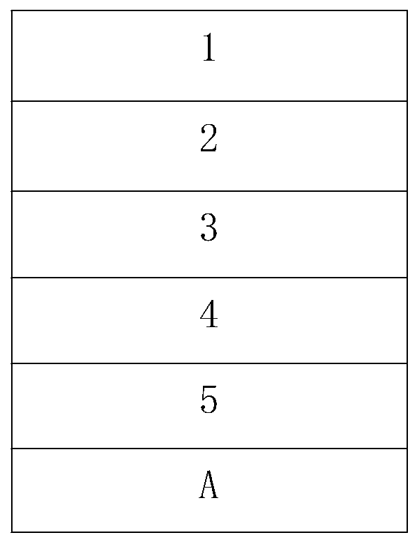
[0028] An anode layer 5 and a hole transport layer 4 were sequentially prepared on the upper surface of the ITO glass substrate, and then a 100 nm thick poly[(2,6-(4,8 -bis(5-(2-ethylhexyl)thiophen-2-yl)benzo[1,2-B:4,5-B']dithiophene)-co-(1,1,3-di(5 -thiophen-2-yl)-5,7-bis(2-ethylhexyl)benzo[1,2-C:4,5-C']dithiophene-4,8-dione)] (referred to as PBDB -T) and (3-(1,1-dicyanomethylene)-1-methyl-indanone)-5,5,11,11-tetrakis(4-hexylphenyl)-dithieno [2,3-d: 2',3'-d']-s-benzobisindeno[1,2-b:5,6-b']-dithiophene) (IT-M for short) film preparation Active layer 3, then functionalized graphene quantum dot solution (concentration of functionalized graphene quantum dots in the solution is 2mg / ml,) is spin-coated on the surface of photoactive layer 3, and the thin film that forms uniform thickness range is 100nm is functionalized then The graphene quantum dots are annealed to obtain the electron transport layer 2, and then transferred to the evaporation system to prepare the cathode layer 1...

Embodiment 2

[0030] With reference to Example 1, the difference is: the functionalized graphene quantum dot solution (the concentration of the functionalized graphene quantum dot in the solution is 100mg / ml,) is spin-coated on the surface of the photoactive layer 3 to form a uniform thickness range of 1nm. film. The I-V test was carried out on the obtained battery, and the circuit current of the device was 16.65mA / cm 2 , the open circuit voltage is 0.91V, the fill factor is 68.84%, and the photoelectric conversion efficiency is 10.43%.

Embodiment 3

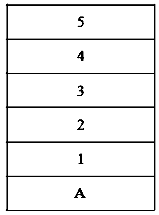
[0032] The cathode layer is prepared on the upper surface of the ITO glass substrate, and the solution of the functionalized graphene quantum dots (the concentration of the functionalized graphene quantum dots in the solution is 0.01mg / ml) is spin-coated on the surface of the cathode layer to form a uniform thickness ranging from 100nm thin film; then the functionalized graphene quantum dots are annealed to obtain the electron transport layer, and then the electron transport layer is spin-coated with a 100nm thick component ratio of 1:1 PBDB-T:IT-M thin film to prepare the photoactive layer. Then prepare a hole transport layer on the other side of the photoactive layer away from the cathode, and then transfer to an evaporation system to evaporate an anode on the surface of the hole transport layer to prepare an anode layer, and prepare an inverted structure of an organic solar cell such as figure 2 As shown, the battery includes a cathode layer 1, an electron transport layer 2...


PUM

PropertyMeasurementUnit
thicknessaaaaaaaaaa
thicknessaaaaaaaaaa
open-circuit voltageaaaaaaaaaa

Abstract

The invention discloses an organic solar cell adopting functionalized graphene quantum dots as an electron transport layer. The cell includes a cathode layer, an electron transport layer, a photoactive layer, a hole transport layer and an anode layer which are in mutual superposition, and a glass substrate; the cathode layer or the anode layer are prepared on the glass substrate; and the electrontransport layer between the cathode layer and the photoactive layer is functionalized graphene quantum dots. Chemical modification treatment can be performed on the graphene quantum dots, and the workcontent of the graphene quantum dots can be adjusted, so that a contact barrier between the active layer and an electrode can be reduced, the collection efficiency of the electrode for photogeneratedcarriers in the cell can be enhanced, and therefore, the graphene quantum dots can be suitable for being the electron transport layer of the cell, and the photoelectric conversion efficiency of the cell can be significantly enhanced while costs are reduced.

Description

Technical field: [0001] The invention relates to an organic solar battery using functionalized graphene quantum dots as an electron transport layer and a preparation method thereof. Background technique: [0002] At present, with the rapid development of the global economy, people's demand for energy is increasing, and energy has become a bottleneck restricting economic development. The decline of traditional energy sources such as oil, coal mines, and natural gas, as well as the environmental pollution caused by their excessive use, have forced people to seek, develop and utilize new, renewable, and environmentally friendly green energy sources. In this context, new green energy sources such as solar energy, wind energy, biomass energy, water energy, and nuclear energy have attracted widespread attention. Among them, solar energy has a series of advantages such as huge reserves, green and harmless, and wide distribution, so it is favored by people. Solar cells can directl...

Claims


Application Information

Patent Timeline
Patent Type & Authority Applications(China)
IPC IPC(8): H01L51/42H01L51/44H01L51/46H01L51/48C09K11/65
CPCY02E10/549
Inventor 张坚胡勇张淑瑶张哲泠
Owner GUILIN UNIV OF ELECTRONIC TECH
Why Eureka
Try Eureka