method for estimating the junction temperature of an IGBT power module on line

A power module and junction temperature technology, applied in the fields of power electronics and electronic information science, can solve problems such as measurement errors affecting estimated values, difficult maintenance, and high failure rate of thermocouples

Inactive Publication Date: 2019-06-11
WUHAN UNIV
View PDF5 Cites 43 Cited by
  • Summary
  • Abstract
  • Description
  • Claims
  • Application Information

AI Technical Summary

Problems solved by technology

[0003] The patent application document with application number 201810036617.7 and publication number 108108573A discloses a dynamic prediction method for junction temperature of IGBT power modules. The junction temperature is calculated based on a fixed thermal model, but it cannot compensate for the heat loss caused by aging and cooling conditions. path degradation
The patent application document with the application number 201710334867.4 and the publication number 107192934A discloses a method for measuring the transient thermal impedance of the high-power IGBT junction, using the thermal parameter method to measure the junction temperature drop of the high-power IGBT during the cooling process At the same time, the thermocouple method is used to obtain the cooling curve of the IGBT case temperature, but the measurement error and the change of working conditions will affect its estimated value, and the thermocouple has a high failure rate and difficult maintenance

Method used


Image

  • method for estimating the junction temperature of an IGBT power module on line
  • method for estimating the junction temperature of an IGBT power module on line
  • method for estimating the junction temperature of an IGBT power module on line

Examples


Embodiment Construction

[0081] Below in conjunction with specific embodiment and accompanying drawing, the present invention will be further described:

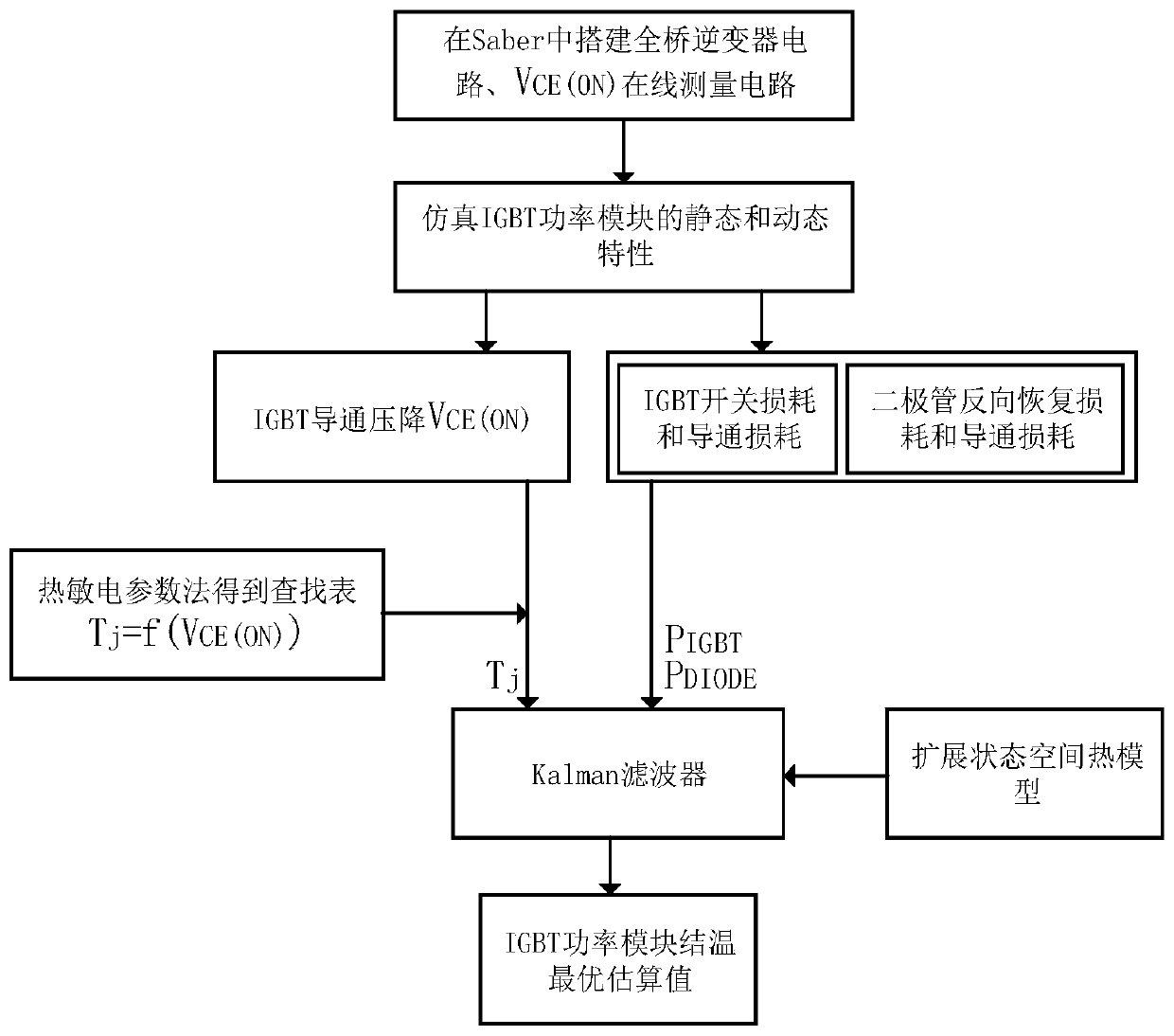
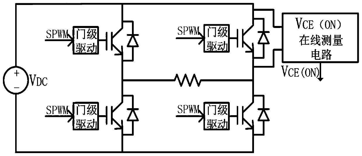
[0082] Such as figure 1 As shown, the present invention provides a method for online estimation of the junction temperature of an IGBT power module, as follows image 3 The shown full-bridge inverter circuit is taken as an example to introduce the implementation process of this method in detail. The specific implementation steps are as follows:

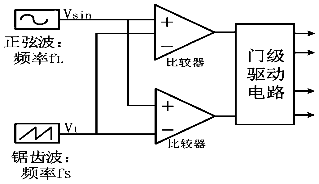
[0083] Step 1. Build a full-bridge inverter circuit in Saber, V CE(ON) On-line measurement circuit, SPWM control circuit and gate-level drive circuit, V CE(ON) The two input terminals of the online measurement circuit are connected to the collector and emitter of the IGBT of the full-bridge inverter circuit to realize the connection between the full-bridge inverter circuit and V CE(ON) Connection of in-line measurement circuits such as figure 2 shown.

[0084] Step 1 in the embodiment specifically inc...


PUM


Abstract

The invention discloses a method for estimating junction temperature on line by an IGBT (Insulated Gate Bipolar Transistor) power module. The method comprises the following steps: estimating the junction temperature by using a thermo-sensitive electrical parameter method; establishing an extended state space thermal model; and applying a Kalman filter in junction temperature estimation. The thermosensitive electrical parameter method can estimate the junction temperature of an IGBT power module in real time, an IGBT conduction voltage drop VCE (ON) is selected as a thermosensitive electrical parameter, and a VCE (ON) online measurement circuit is provided. On the basis of a Foster thermal network model, the influence of diode coupling is considered, and an extended state space thermal model comprising self-heating and coupling heat is provided; And taking the power loss of the diode and the IGBT and the junction temperature estimation value obtained by using the thermosensitive electrical parameter method as the input of the Kalman filter, and considering the measurement noise and the process noise, thereby obtaining the optimal junction temperature estimation value. According to the method, electrical insulation is achieved, measurement is carried out without changing a control strategy of the power converter, noise is reduced, the intermittent influence of voltage measurementis eliminated, and the junction temperature measurement precision is improved.

Description

technical field [0001] The invention belongs to the field of power electronics and electronic information science, and specifically relates to a method for online estimation of junction temperature of an IGBT power module, which uses a Kalman filter to obtain an optimal estimation value of the junction temperature. Background technique [0002] Power converters are widely used in the fields of smart grid, rail transit and new energy, and insulated gate bipolar transistors (IGBTs) are the key components of power converters, and their reliability is the guarantee for safe operation of the system. Therefore, the status monitoring and life prediction of IGBT are extremely important. There are many failure forms of IGBT power modules, and temperature is the main factor leading to its failure. Therefore, thermal analysis is an important content in the status evaluation of IGBT power modules. Real-time measurement of IGBT power modules The junction temperature is of great significa...

Claims


Application Information

Patent Timeline
Patent Type & Authority Applications(China)
IPC IPC(8): G06F17/50G06F17/11G06F17/15G06F17/16
CPCG01K7/01G01K7/42G01K2217/00G01K7/015G01K13/00G06F17/10G06F17/15
Inventor 何怡刚李凯伟袁伟博何鎏璐郭宇铮张慧
Owner WUHAN UNIV
Why Eureka
Try Eureka