
Activated carbon regeneration device and method based on self-sustaining combustion

A regeneration device, activated carbon technology, applied in separation methods, filter regeneration, combustible gas purification, etc., can solve the problems of difficult to guarantee the uniformity of regeneration effect, high energy consumption of heating regeneration method, harsh regeneration conditions, etc., to shorten the heat transfer. Time required, efficient regeneration, fast regeneration effect

Inactive Publication Date: 2019-07-09
QINGDAO INST OF BIOENERGY & BIOPROCESS TECH CHINESE ACADEMY OF SCI
View PDF10 Cites 0 Cited by
  • Summary
  • Abstract
  • Description
  • Claims
  • Application Information

AI Technical Summary

Problems solved by technology

[0004] At present, the regeneration methods of waste activated carbon mainly include technologies such as heating regeneration, chemical regeneration, and biological regeneration, but these technologies have more or less problems such as harsh regeneration conditions, low regeneration efficiency, long running time, high energy consumption, and secondary pollution.
Taking the most commonly used heating regeneration technology as an example, the inventors found that due to the need for an external heating source and continuous supply of steam or inert gas, the heating regeneration method consumes a lot of energy, and the regeneration cost is about 60% to 80% of fresh activated carbon.
In addition, affected by the heating method, the uniformity of the regeneration effect is often difficult to guarantee

Method used


Image

  • Activated carbon regeneration device and method based on self-sustaining combustion
  • Activated carbon regeneration device and method based on self-sustaining combustion
  • Activated carbon regeneration device and method based on self-sustaining combustion

Examples


Embodiment 1

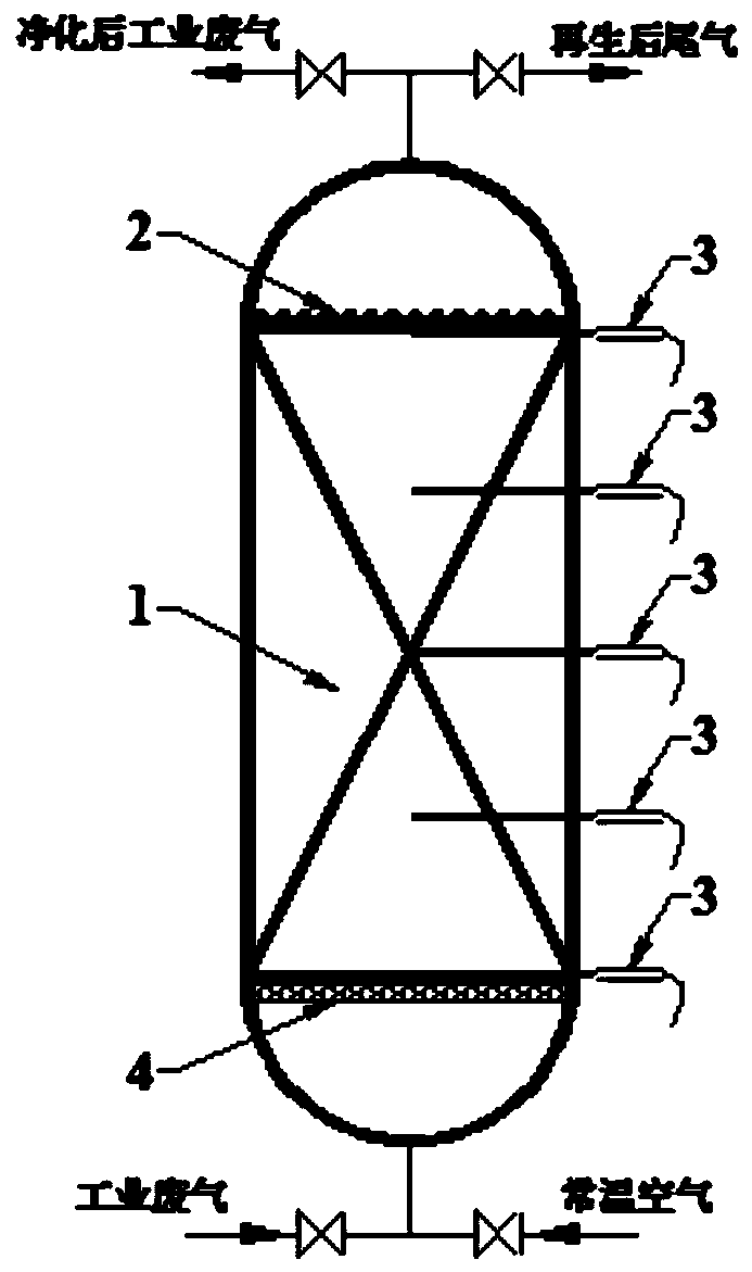
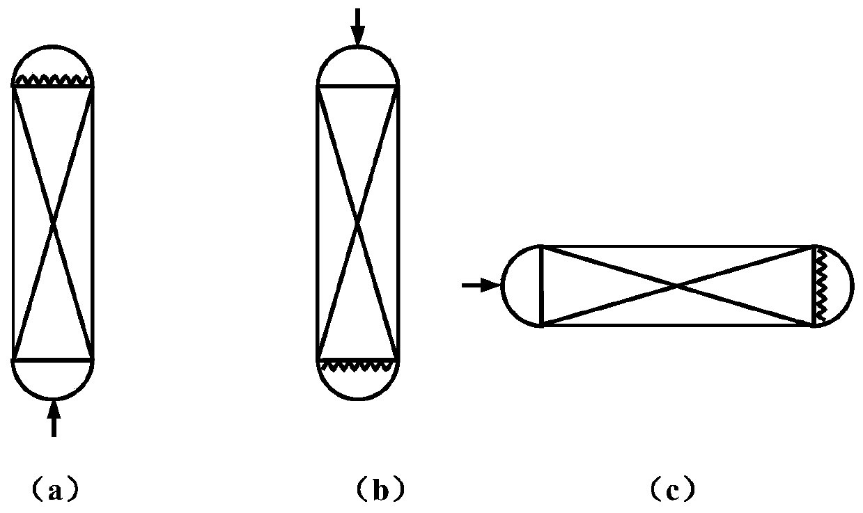
[0076] In embodiment one, as attached figure 1 As shown, a waste activated carbon regeneration device based on self-sustaining combustion is provided, and the device includes an oxidant pipeline connected to the industrial waste gas input end of a conventional activated carbon adsorption bed, and an ignition device electric heating wire is arranged on the output end side, and the waste activated carbon regeneration device Arrange thermocouple sensors and observation windows along the flow direction of the oxidant, and install an air distribution plate on the side of the input end; based on this device, a waste activated carbon (activated carbon particle size of 10-24 mesh) saturated with ethanol was burned through regeneration experiments. During regeneration, the superficial flow velocity of normal temperature air passing into the spent activated carbon bed is 0.065m / s. In order to investigate the effectiveness of the through-type combustion regeneration method, an adsorptio...

Embodiment 2

[0086] In embodiment two, the waste activated carbon used is the same as that in embodiment one, that is, the saturated waste activated carbon (10-24 mesh) that has adsorbed ethanol. At this time, the superficial flow velocity of the air in the regeneration process is controlled to be 0.033m / s. In combination with Example 1 and Example 2, the effect of air flow on the regeneration effect of waste activated carbon adsorbing ethanol will be investigated. The data of the waste activated carbon after four regeneration-adsorption cycle experiments are shown in Table 2.

[0087] It can be seen from Table 2 that after reducing the regeneration air flow rate to 0.033m / s, the adsorption performance of regenerated activated carbon on ethanol is slightly reduced, which is mainly manifested in the reduction of adsorption capacity. However, compared with fresh activated carbon, the reduction rate of activated carbon's adsorption capacity for ethanol after four regenerations was less than ...

Embodiment 3

[0091] In Example 3, a regeneration experiment of penetrating combustion was carried out on another kind of saturated waste activated carbon (the particle size of the activated carbon is 4-6 meshes) that had adsorbed ethanol. At this time, the superficial flow velocity of the air in the regeneration process is controlled to be 0.065m / s. In conjunction with Example 1, this example will examine the applicability of the regeneration method to different activated carbons. The data of the waste activated carbon after five regeneration-adsorption cycle experiments are shown in Table 3.

[0092] For the waste activated carbon, the through-type combustion can still realize its high-efficiency regeneration: 1) The adsorption capacity and adsorption rate of the activated carbon after regeneration are improved, and it is still better than that of fresh activated carbon after five regenerations; 2) After five regenerations, the activated carbon average The single loss rate is 4.56%, whic...


PUM

PropertyMeasurementUnit
Adsorption rateaaaaaaaaaa
Particle sizeaaaaaaaaaa
Adsorption capacityaaaaaaaaaa

Abstract

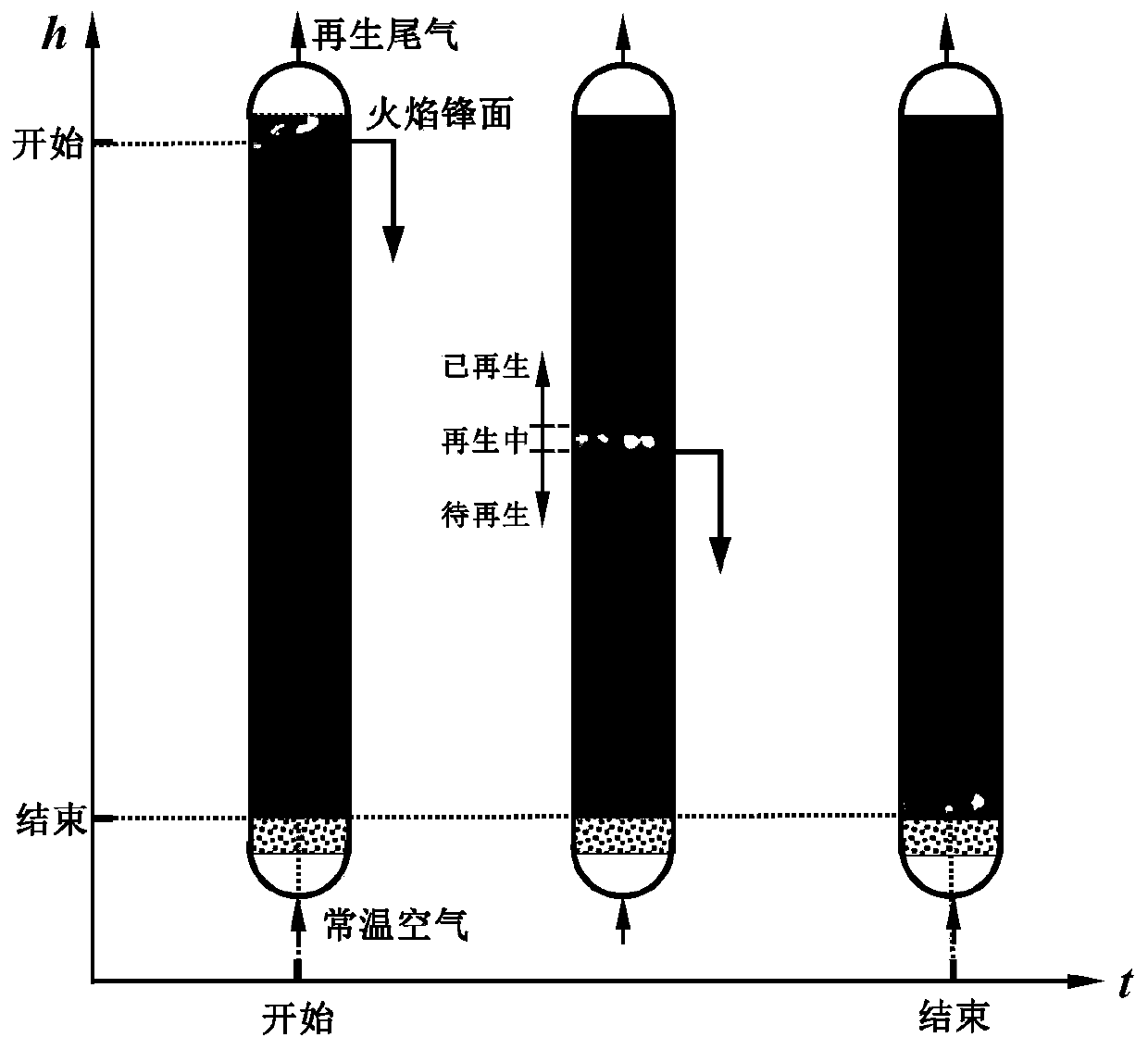
The invention provides an activated carbon regeneration device and method based on self-sustaining combustion. The method mainly aims at efficient regeneration of waste activated carbon adsorbing volatile organic compounds or gaseous inorganic compounds, an oxidizing agent is introduced into one side of a waste activated carbon particle fixed bed, an ignition device is arranged on the other side of the waste activated carbon particle fixed bed, and a plurality of thermocouple sensors and observation windows are arranged in the flowing direction of the oxidizing agent to monitor the combustionprocess. According to the invention, self-maintaining oxygen-deficient combustion is realized in the activated carbon bed by reasonably controlling the flow of the oxidizing agent; the formed flame penetrates through the whole bed layer; according to the present invention, the flame can move towards the oxidizing agent incoming flow direction so as to achieve the regeneration of the waste activated carbon, and the generated regenerated tail gas can be directly recycled or combusted so as to meet the regeneration requirements of the waste activated carbon in chemical industry, environmental protection industry, power plant industry, petrochemical industry, furniture industry and other industries, such that the device and method have good practical application values.

Description

technical field [0001] The invention belongs to the technical field of environmental protection and energy saving, and in particular relates to an activated carbon regeneration device and method based on self-sustaining combustion. Background technique [0002] The information disclosed in this background section is only intended to increase the understanding of the general background of the present invention, and is not necessarily taken as an acknowledgment or any form of suggestion that the information constitutes the prior art already known to those skilled in the art. [0003] In the face of increasingly severe environmental protection pressure, the efficient adsorption performance of activated carbon is used to remove harmful gases such as volatile organic compounds (VOCs) in industrial waste gas, to treat harmful substances such as heavy metals in industrial sewage, and to remove CO in the process of fossil fuel utilization. 2 Capture has become an important measure t...

Claims


Application Information

Patent Timeline
IPC IPC(8): B01J20/34
CPCB01J20/3416B01J20/3483
Inventor 齐晓宾高健
Owner QINGDAO INST OF BIOENERGY & BIOPROCESS TECH CHINESE ACADEMY OF SCI
Learn More