
TiB<w>-Ti composite layer and laser in-situ preparation method thereof

A composite layer and laser technology, applied in coating, metal material coating process, etc., can solve the problems of loose and porous titanium-based composite materials, increased cost, high chemical stability, etc.

Active Publication Date: 2019-07-09
PUTIAN UNIV
View PDF10 Cites 5 Cited by
  • Summary
  • Abstract
  • Description
  • Claims
  • Application Information

AI Technical Summary

Problems solved by technology

[0004] At present, although TiBw / Ti composites with heterogeneous structure can be prepared by hot pressing sintering, smelting, and powder metallurgy, the obtained titanium-based composites have problems such as looseness, porosity, and reinforcement phase agglomeration. Deformation and subsequent heat treatment
This not only increases the cost of multiple processes, but also easily leads to unstable organizational structure.
(2) Partially layered Ti-TiBw / Ti composites can be prepared by reactive hot pressing sintering and diffusion bonding, but the interface bonding between layers is not complete metallurgical bonding, and the interface bonding strength still needs to be further improved, and the layered The surface is mainly Ti-based material, which is not conducive to the application of anti-oxidation and anti-wear
(3) The traditional preparation technology cannot effectively become the surface modification and repair technology of titanium alloy. Even if the TiBw / Ti composite coating with non-uniform distribution can be successfully prepared on the surface of titanium alloy, it may damage the titanium alloy to a large extent. The original properties of the alloy base material, such as hot pressing sintering, smelting and powder metallurgy technology
Although TiB 2 Hardness without BN and B 4 C high, but TiB 2 The chemical stability is high, and TiB 2 The density and thermal expansion coefficient are similar to those of TiB and Ti

Method used


Image

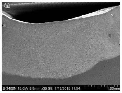
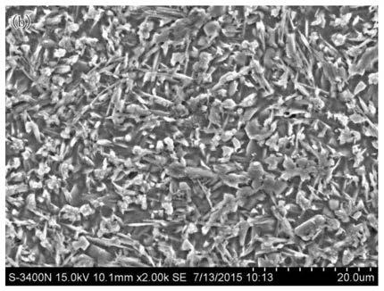
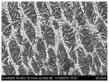
  • TiB&lt;w&gt;-Ti composite layer and laser in-situ preparation method thereof
  • TiB&lt;w&gt;-Ti composite layer and laser in-situ preparation method thereof
  • TiB&lt;w&gt;-Ti composite layer and laser in-situ preparation method thereof

Examples


preparation example Construction

[0054] The above-mentioned laser in-situ preparation method can be realized by the following reaction equipment: the equipment includes: (A) a laser beam as a heat source; (B) a coaxial powder feeder for inputting raw materials; Replacement protection; (D) an induction heating device for heating the substrate and monitoring the temperature in real time.

[0055] In this method, firstly, by adjusting the composition ratio and laser parameters, the TiB from the surface to the inside is obtained. 2 The melted layer with reduced content gradient and increased Ti grain size gradient; secondly, by selecting a lower laser energy density to induce remelting from the top of the melted layer to the adjacent middle position, a structure with increased TiBw content and reduced Ti grain size is obtained The remelted layer of the structure; finally, through the synergy of induction heating and laser quenching, the residual β-Ti in the remelted layer and the molten layer is transformed into ...

Embodiment 1

[0068] (1) Preliminary preparation: Ti-6Al-4V alloy is selected as the substrate, and its composition is Ti-6.01Al-3.84V-0.3Fe-0.15S-0.1C-0.1O-0.15Ni in weight percentage. The titanium alloy substrate is placed in a closed atmosphere controllable processing protection chamber, and the induction heater is placed on the lower part of the substrate and fastened.

[0069] Choose pure TiB with argon atomization size of 75μm~48μm and purity of 99.9% 2 and pure Ti powder with a purity of 99% as the cladding material, the TiB 2 The mass-component ratio of Ti powder and Ti powder is 6:1. The two materials are mixed for 120 minutes with a vertical high-energy ball mill, and placed in a drying box for 60 minutes at 120°C, and then put into a coaxial powder feeder. High-purity argon with a purity of 99.9% is selected as the protective gas and powder conveying gas.

[0070] (2) Prepare the melting layer: The laser melting process parameters are: the laser beam spot size is 5×5mm (square ...

Embodiment 2

[0076] (1) Preliminary preparation: TA2 titanium alloy is selected as the substrate, and its composition is Ti-0.03N-0.015H-0.3Fe-0.25O-0.1C in weight percentage.

[0077] Choose pure TiB with argon atomization particle size of 70μm~50μm and purity of 99.9% 2 And pure Ti powder with a purity of 99.1% is the cladding material. TiB 2 The mass-to-component ratio of Ti powder is 4:1, and the two materials are mixed for 150 minutes with a vertical high-energy ball mill, placed in a drying oven at 120°C for 90 minutes, and then put into a coaxial powder feeder. High-purity argon with a purity of 99.99% is selected as the protective gas and powder conveying gas.

[0078] (2) Preparation of melting layer: laser melting process parameters are: laser beam spot diameter is 4mm (circular spot), laser power is 2.5-2.6kW, scanning speed is 4mm / s, powder feeding rate is about 20g / min, defocus amount -1mm, the thickness of the molten layer is about 1.9-2.1mm. The melting layer has TiB fro...


PUM

PropertyMeasurementUnit
Thicknessaaaaaaaaaa
Diameteraaaaaaaaaa
Sizeaaaaaaaaaa

Abstract

The invention provides a TiB<w>-Ti composite layer and a laser in-situ preparation method thereof. Specifically, the composite layer is prepared from the raw materials: Ti powder and TiB2 powder, a melting layer with a gradient change of TiB<w> / Ti content is prepared on the surface of a substrate, the melting layer is remelted, and a cladding layer is prepared on the surface of a remelting layer by means of a synergistic effect of induction heating and laser quenching. In the cladding layer, the interface structure of alpha-Ti and TiB<w> is in the form of coherent combination or semi-coherentcombination, and the strength and toughness, the high-temperature oxidation resistance, the fretting abrasion resistance and the fretting fatigue resistance can be remarkably improved. The TiB<w>-Ti composite layer can be widely applied to a modification layer and a repair layer of an aircraft engine shell auxiliary part made of a titanium alloy material.

Description

technical field [0001] The invention relates to the technical field of composite materials, in particular to a TiBw-Ti composite layer and a method for preparing the TiBw-Ti composite layer by adopting laser in-situ technology. Background technique [0002] As a reinforcing phase, TiBw has been widely used in titanium matrix composites. According to the reinforcing phase generation method, it can be divided into external addition method and in situ reaction self-generation method. Due to the difficulty in the preparation of TiBw powder, currently TiBw-reinforced titanium matrix composites are basically prepared by in-situ reaction autogenous method. Raw materials commonly used as B source are ZrB 2 , B 4 C, BN, TiB 2 、LaB 6 And B powder, etc. At present, the main preparation technologies for producing TiBw-reinforced titanium-based composites by in-situ methods include: powder metallurgy, mechanical alloying, self-propagating high-temperature synthesis technology, exoth...

Claims


Application Information

Patent Timeline
IPC IPC(8): C23C24/10C22F1/18
CPCC22F1/183C23C24/103
Inventor 林英华林振衡陈庆堂唐群华雷永平
Owner PUTIAN UNIV
Learn More