Grinding belt-type device for rapid catalytic pyrolysis of biomass and method

A technology for catalytic pyrolysis and biomass, which is applied in the field of biomass energy utilization, can solve the problems of difficulty in ensuring the catalytic effect of catalysts, difficulty in condensing pyrolysis gas, and large loss of condensation heat, and achieves convenient regulation, compact structure, and increased processing capacity. Effect

Active Publication Date: 2019-07-12
北京博霖环境科技有限公司
View PDF6 Cites 4 Cited by
  • Summary
  • Abstract
  • Description
  • Claims
  • Application Information

AI Technical Summary

Problems solved by technology

[0004] As for the catalytic pyrolysis technology of biomass, the current mainstream pyrolysis reactors are analyzed: for kinetic mechanical reactors, such as rotating cones and ablation reactors, although they have low energy consumption and compact structure, they can be strengthened by rotating centrifugation. wall heat exchange, but it is difficult to ensure the catalytic effect of the catalyst on the inside of the particles by centrifugal force alone; for the pressure roller reactor, although the raw material particles can be heated up rapidly by forced rolling, the raw material particles also become tight during the rolling process. In fact, it is also difficult to catalyze the internal reaction of the particles; for the fluidized bed reactor, through the collision of the raw material particles and the heat carrier, it can continuously peel off the remaining carbon from the pyrolysis on the surface of the raw material while ensuring high-efficiency heat transfer, so that the catalytic effect continues to penetrate Correspondingly, problems such as difficulty in condensation of pyrolysis gas caused by large amount of carrier gas, large loss of condensation heat, serious wear of the reactor, and large equipment also limit the development of fluidized bed reactors.

Method used


Image

  • Grinding belt-type device for rapid catalytic pyrolysis of biomass and method
  • Grinding belt-type device for rapid catalytic pyrolysis of biomass and method
  • Grinding belt-type device for rapid catalytic pyrolysis of biomass and method

Examples


Embodiment 1

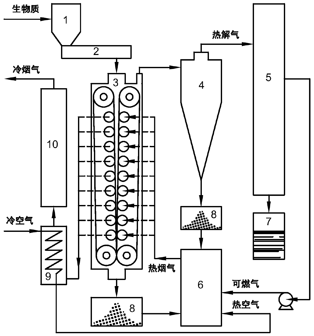
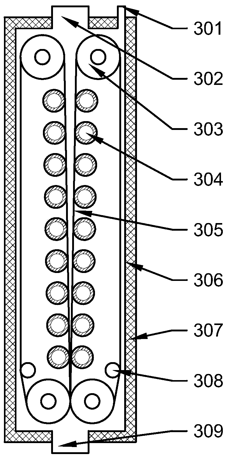
[0047] Walnut shells with a moisture content of 6wt% are crushed to an average particle size of 10mm, passed through the screw feeding system 2 at a feed rate of 150kg / h, and then entered into the abrasive belt pyrolysis reactor 3; the abrasive belt 305 is all friction layers , prepared by using friction coating; the grinding belt on one side adopts a downward running speed of 10m / min, and the grinding belt on the other side adopts an upward running speed of 6m / min; the temperature of the flue gas entering the grinding belt pyrolysis reactor 3 is 740°C , the temperature in the pyrolysis reactor was measured to be 510°C; after the pyrolysis product was separated from gas and solid and condensed, a three-phase pyrolysis product was obtained, wherein the yield of coke was 27.1wt%, and the yield of bio-oil was 52.1wt%. The combustible gas yield was 20.8 wt%.

Embodiment 2

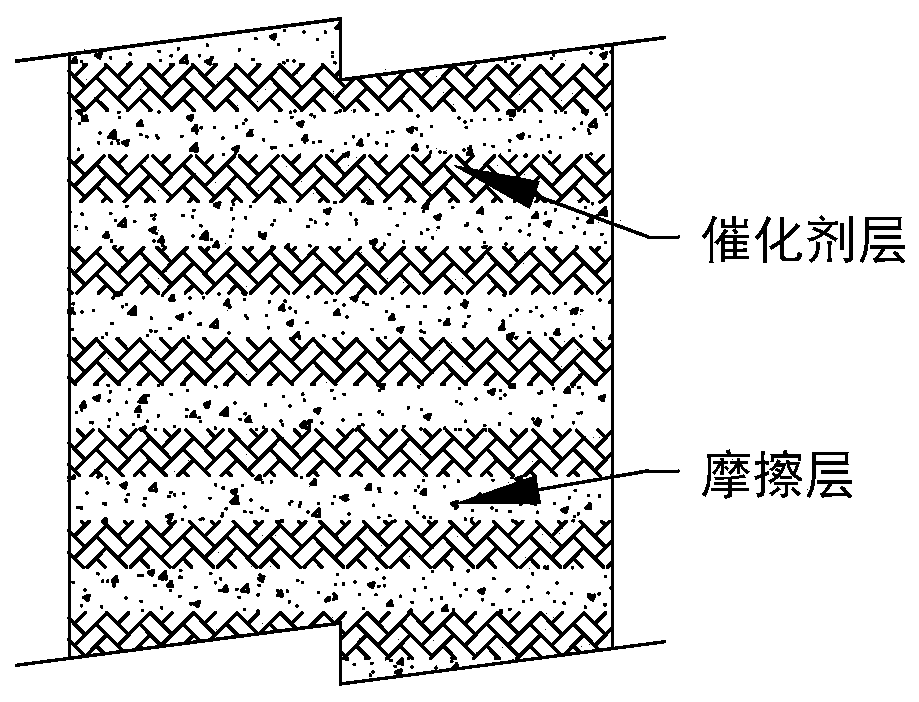
[0049] Poplar with a moisture content of 8wt% is crushed to an average particle size of 10 mm, and fed into the grinding belt pyrolysis reactor 3 through the screw feeding system 2 at a feed rate of 100 kg / h; the grinding belt 305 adopts a catalytic type , and the friction layer and the catalyst layer are arranged alternately at an interval of 10mm; the friction layer is made of friction coating, and the catalyst layer is loaded on the grinding belt by solid phosphoric acid; one side of the grinding belt runs downward at a speed of 16m / min, and the other side of the grinding belt runs upward at 12m / min; the flue gas temperature entering the heating pipe 304 is 450°C, ensuring that the temperature in the pyrolysis reactor is maintained at 300°C; the pyrolysis product is obtained after gas-solid separation and pyrolysis gas condensation Bio-oil of glucosone, the yield of L-glucosone is 8.1wt%.

Embodiment 3

[0051] The corncob that moisture content is 6wt% is crushed to the average particle diameter and is 10mm; Send into grinding belt type pyrolysis reactor 3 with feed rate 120kg / h by screw feed system 2 subsequently; By regulating motor power, ensure The grinding belt on one side runs downward at a speed of 12m / min, and the grinding belt on the other side runs upward at a speed of 8m / min; the friction belt only uses the friction coating, and the catalyst ZnCl 2 Introduced by directly impregnating raw materials during raw material pretreatment, the measured load is 16.3wt%; the temperature of the flue gas entering the grinding belt pyrolysis reactor 3 is 510°C, and the temperature in the pyrolysis reactor is 340°C; After the pyrolysis product is separated from gas and solid and condensed from the pyrolysis gas, the three-phase pyrolysis product of solid, liquid and gas is obtained, and the yields of each are 44.2%, 46.5% and 9.3%, respectively, and the yield of the target product ...


PUM


Abstract

The invention belongs to the field of biomass energy utilization, and relates to a grinding belt-type device for rapid catalytic pyrolysis of biomass and a method. The device comprises a hopper, a feed system, a grinding belt-type pyrolysis reactor, a gas-solid separation system, a pyrolysis gas condensation system, a combustion system, a bio-oil collection tank, a charcoal collection tank, an airpreheating system and a flue gas purification system, wherein the grinding belt-type pyrolysis reactor comprises grinding belts, heating tubes, driving drums, tensioning devices, a sealed casing, a feed inlet, a discharge opening and a gas outlet. Pretreated material particles are continuously sheared and rubbed by the grinding belts with speed difference on two sides, and are heated by the multi-layer heating tubes to continuously pyrolyze on the surface while stripping the residual charcoal, so that a catalyst and heat can be fully fed inside the particles; the pyrolysis gas is rapidly condensed by gas-solid separation to obtain high-grade bio-oil fuel or bio-oil rich in specific high value-added products; combustible gas and coke produced by combustion generate high-temperature flue gas for heating the heating tubes, so as to achieve an autothermal pyrolysis process.

Description

technical field [0001] The invention belongs to the technical field of biomass energy utilization, and in particular relates to a belt-grinding biomass fast catalytic pyrolysis device and method. Background technique [0002] With the increasingly serious energy shortage and environmental pollution in today's society, compared with other renewable energy sources, biomass is gradually developing in the direction of replacing traditional fossil energy due to its energy carrier characteristics; and pyrolysis technology will It is one of the effective methods for converting biomass raw materials into high-efficiency energy substances such as gas and liquid fuels. In addition, through the directional control of biomass pyrolysis process by using catalysts, bio-oil rich in specific chemicals can be selectively prepared, which also heralds its unlimited potential to replace petrochemicals for the production of chemical raw materials. The key to large-scale and industrial applicati...

Claims


Application Information

Patent Timeline
Patent Type & Authority Applications(China)
IPC IPC(8): C10B53/02C10G1/00
CPCC10B53/02C10G1/00Y02E50/10
Inventor 陆强谢文銮王则祥李洋杨勇平
Owner 北京博霖环境科技有限公司
Why Eureka
Try Eureka