

Control method of heat pump system
A control method and technology for a heat pump system, applied in the field of heat pump systems, can solve the problems of easy frost formation in winter, poor low temperature performance, etc., and achieve the effects of accuracy and real-time performance, stable operation state, and realization of utilization.
- Summary
- Abstract
- Description
- Claims
- Application Information
AI Technical Summary
Problems solved by technology
Method used
Image

Examples
Embodiment 1
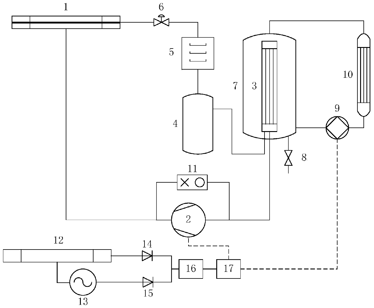
[0029] A control method for a heat pump system, such as figure 1 As shown, including PV / T system, heating system, power supply system and control system.
[0030] The PV / T system includes a PV / T heat collector, a compressor, a condenser, a liquid receiver, a dry filter, an expansion valve, a heat storage tank, a drain valve, and a pressure protector. Refrigerant is selected as the circulating working medium of the system. The working medium absorbs solar energy and heat in the air and evaporates in the PV / T heat collector, and then enters the compressor to become high-temperature and high-pressure steam, and then enters the condensation pipe to condense Heat release, the condensing pipe is set inside the heat storage water tank, the heat released by the condensing pipe heats the water in the water tank, and finally the working fluid that turns back into liquid flows through the liquid storage, dry filter, expansion valve, throttling drop Return to the PV / T heat collector afte...
Embodiment 2
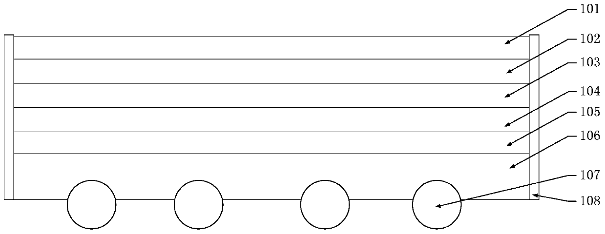
[0037] A PV / T collector, such as figure 2As shown, it includes glass cover plate, air channel, EVA, photovoltaic cell, TPT back plate, new controllable phase change heat storage plate, evaporation tube, aluminum alloy frame arranged in sequence from top to bottom, and sunlight shines on the glass cover plate In the above, the photovoltaic cell adopts a monocrystalline silicon cell, which is converted into electrical energy by absorbing sunlight, and then converts the electrical energy into thermal energy and stores it in a new type of controllable phase change heat storage plate, and the new controllable phase change heat storage plate and evaporation The combination of tubes adopts the tube-sheet type, and then the heat of the new controllable phase-change heat storage plate is transferred to the evaporation tube through switch control. The evaporation tube can absorb both solar heat and heat in the air, and then transfer it to the evaporation tube The refrigerant working me...
Embodiment 3
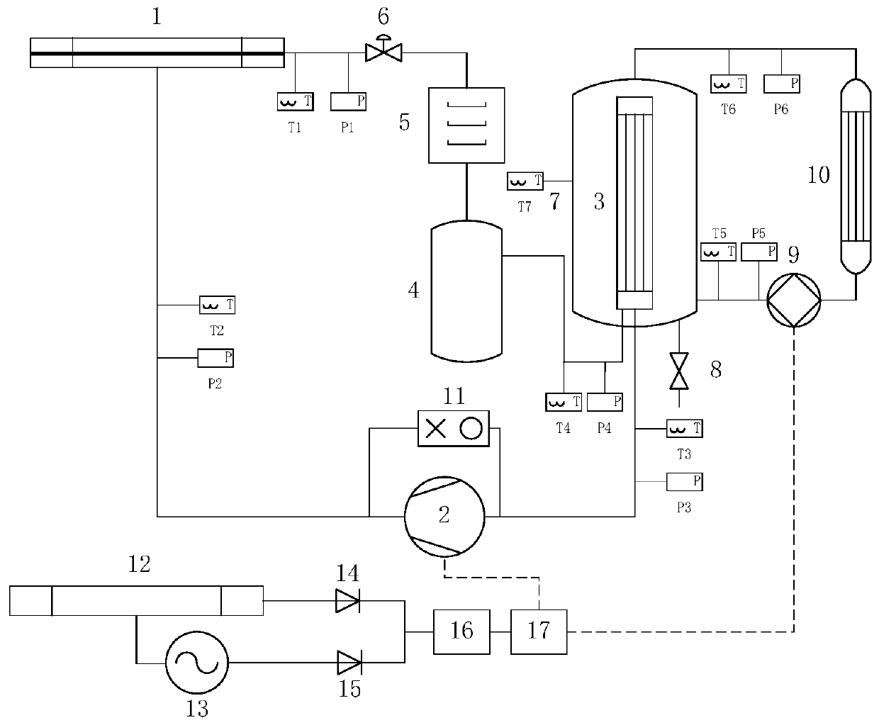
[0039] The measuring point layout of the photovoltaic photothermal composite air source heat pump system of the present invention is as follows: image 3 As shown, the control system includes an intelligent controller, PV / T heat collector inlet temperature T1 and pressure P1, compressor inlet temperature T2 and pressure P2, outlet temperature T3 and pressure P3, condensing coil outlet temperature T4 and pressure P4 , the outlet temperature T5 and pressure P5 of the heat storage water tank, the inlet temperature T6 and pressure P6, and the temperature of hot water in the heat storage water tank T7.
[0040] According to the weather conditions and collected data, the following heat collection strategies are adopted:
[0041] 1) When the solar radiation is strong and the temperature T1 of the refrigerant in the condensation section is higher than the temperature T7 of the cooling water in the water tank, the system operates in the mode of solar photovoltaic-evaporation pipe-conde...
PUM
 Abstract
Description
Claims
Application Information