
Automatic oily sludge treatment system and treatment process

A treatment system and oil sludge technology, applied in the direction of incinerator, combustion method, combustion type, etc., can solve the problems of complex process, long process, high failure rate of equipment, etc., and achieve improved treatment efficiency, low smoldering temperature and good treatment effect Effect

Pending Publication Date: 2019-08-16
CHINA UNIV OF PETROLEUM (EAST CHINA)
View PDF0 Cites 0 Cited by
  • Summary
  • Abstract
  • Description
  • Claims
  • Application Information

AI Technical Summary

Problems solved by technology

Among them, the incineration method produces harmful gases such as sulfur and nitrogen, causing secondary pollution; the biological treatment method needs to mix the oily sludge with loosening agent, fertilizer and inoculation liquid, often vibrate and ventilate naturally, and it takes 41 days to remove 97% The biodegradation of petroleum hydrocarbons, the same oil resources have not been recycled; the hot washing method is suitable for oily sludge with less clay content and higher oil content, but the drainage and residue need to be further treated; the problem with the solvent extraction method is that the process is long , the process is complicated and the treatment cost is high, and it is only suitable for oily sludge containing a large amount of organic matter that is difficult to degrade; the chemical demulsification method requires additional demulsifiers and heating for severely emulsified oily sludge; the solid-liquid separation method is for high oil content and pollution Severe oily sludge, low oil recovery rate; solidified landfill method has simple process, low investment, and large processing capacity, but it is difficult to coat petroleum, and there is a risk of secondary pollution; superheated steam method is fully contacted through the nozzle Oily sludge, oil-water and solid separation, high separation efficiency, but small scale, high cost, high equipment failure rate; pyrolysis method is to decompose macromolecular organic matter into small molecular hydrocarbons and coke under the condition of no oxygen and high temperature, which has great influence on the process , equipment and safety requirements are high, the quality of oil and gas is poor, the odor is strong, and the residue is still hazardous waste
[0004] It can be seen that the above-mentioned prior art method has not been popularized and applied in China due to reasons such as investment, treatment effect and secondary pollution.

Method used


Image

  • Automatic oily sludge treatment system and treatment process
  • Automatic oily sludge treatment system and treatment process
  • Automatic oily sludge treatment system and treatment process

Examples


Embodiment 1

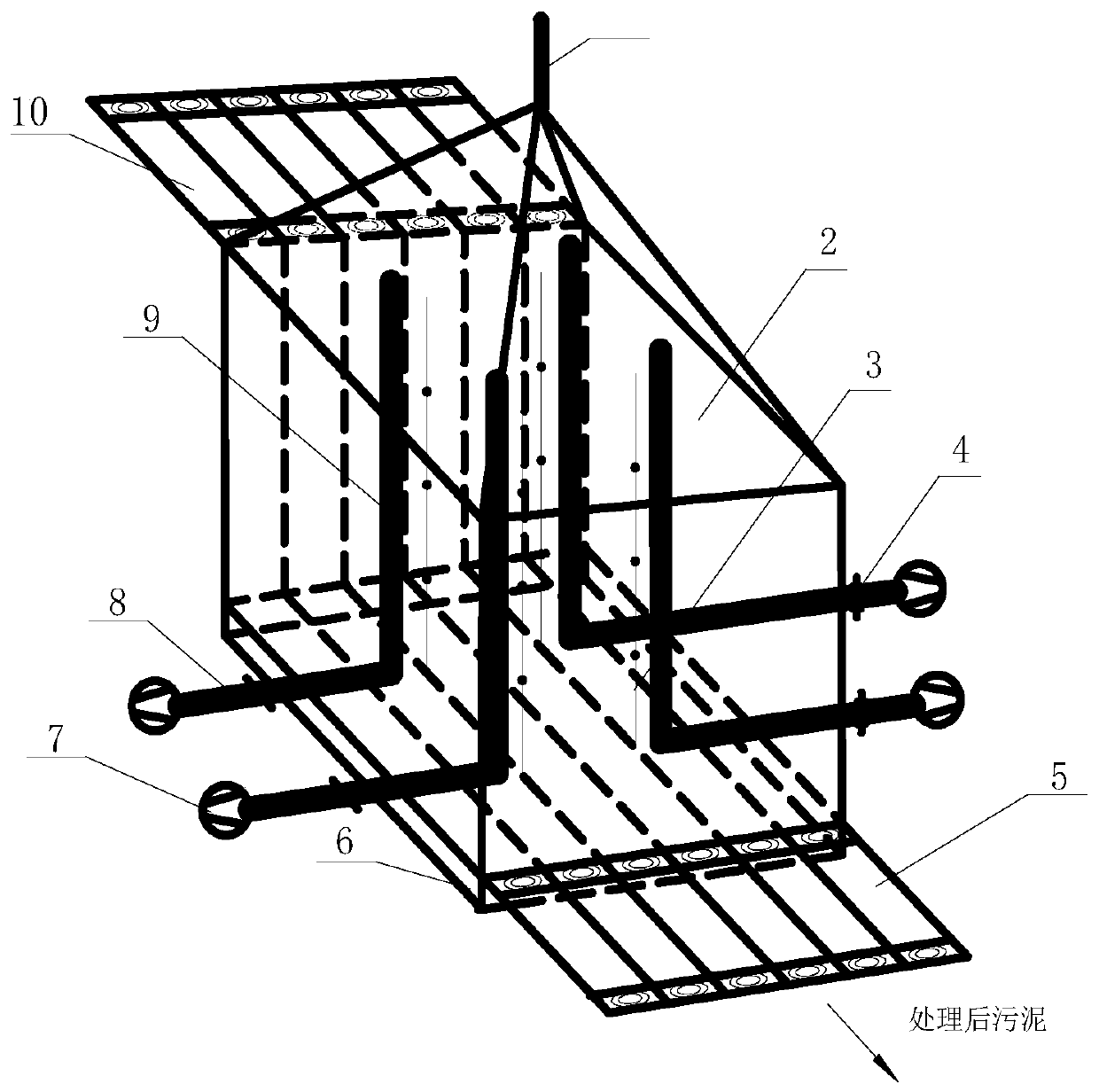
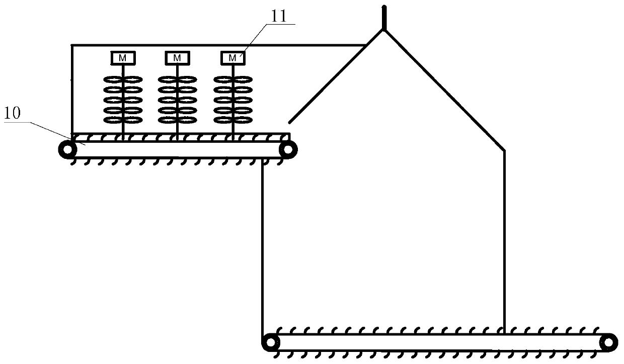
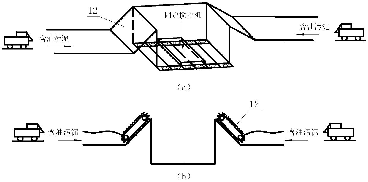
[0033] An automatic treatment system for oily sludge, which includes an oily sludge combustion system, an oily sludge delivery system, an oily sludge mixing system, and an oily sludge feeding system. The oily sludge feeding system sends oily sludge into the oily sludge mixing system through an oily sludge delivery system; image 3 As shown, the oily sludge is transported to the sludge feeding system by the sludge truck, and a primary conveyor belt 12 is arranged between the sludge feeding system and the sludge mixing system, and the oily sludge is sent into the sludge mixing system through the primary conveyor belt 12, The oily sludge mixing system is provided with a mixer 11, and the oily sludge therein is stirred by the mixer 11, so that the organic matters in the oily sludge are distributed as evenly as possible.

[0034] A secondary conveyor belt 10 is arranged between the sludge mixing system and the sludge combustion system, and the stirred sludge is transported to the co...

Embodiment 2

[0041] The difference from Example 1 is that the oily sludge automatic treatment system can also include an automatic control system to realize centralized treatment and automatic treatment of sludge. The automatic control system, for example, uses a computer to feed the oil sludge combustion system and oil sludge. After the system is controlled and certain parameters are set, the pipeline-type low-temperature combustion treatment of oily sludge can be realized.

[0042] The advantage of the present invention is that it can realize centralized and automatic treatment of large quantities of oily sludge, and by means of the oily sludge feeding system, oily sludge mixing system, etc., only need to control the amount of oily sludge at the inlet of the oily sludge to realize the low-temperature combustion treatment of the oily sludge assembly line . Holes are opened on the heating tube, which can evenly and fully disperse the hot air to the surface of the oil sludge to be treated, ...


PUM

PropertyMeasurementUnit
Lengthaaaaaaaaaa

Abstract

The invention discloses an automatic oily sludge treatment system and treatment process, and relates to the technical field of oily sludge treatment. The automatic oily sludge treatment system comprises an oily sludge combustion system, an oily sludge conveying system, an oily sludge stirring system and an oily sludge feeding system, wherein the oily sludge combustion system comprises a combustionchamber, a heating device and a temperature measuring device; the combustion chamber comprises a chamber body and a chamber cover; the heating device comprises a plurality of heating tubes; each heating tube consists of a first heating tube and a second heating tube; the first heating tube is positioned outside the chamber body; the first heating tube is connected with an air inlet tube; the second heating tube is positioned inside the chamber body; an opening is formed in the second heating tube; an air heater is arranged at the end, away from the chamber body, of the first heating tube; airfed through the air inlet tube is heated by the air heater and is discharged through openings after passing through the first heating tube and the second heating tube; and a tail gas collecting tubeis connected on the chamber cover and is used for discharging gas generated in the combustion process through the oily sludge combustion system. The automatic oily sludge treatment system and treatment process have the advantages of low cost, high environment friendliness and good treatment effect.

Description

technical field [0001] The invention relates to the technical field of oily sludge treatment, in particular to an automatic oily sludge treatment system and a treatment process. Background technique [0002] A large amount of oily sludge is often produced in the process of crude oil extraction, oil field gathering and transportation, and sewage treatment. According to statistics, the total amount of oily sludge produced in my country every year reaches more than 5 million tons, and with the deep exploitation of most oil fields, the output of oily sludge will continue to increase. If it is directly discharged, it will occupy a large amount of land, and the toxic substances it contains will pollute the water, soil and air, and deteriorate the ecological environment; when it is directly used for reinjection and circulation in the sewage treatment system, it will cause the quality of the injected water to decline and the operation of the sewage treatment system Conditions deter...

Claims


Application Information

Patent Timeline
IPC IPC(8): F23G7/00
CPCF23G7/001F23G2204/20F23G2205/122F23G2207/101
Inventor 蒋文明王天宇刘杨邓展飞丁聚华
Owner CHINA UNIV OF PETROLEUM (EAST CHINA)
Learn More