Micro lens mask and preparation method thereof

A technology of microlens and reticle, applied in the field of microlens reticle and its preparation, can solve the problem of non-reusable microsphere array reticle, low efficiency of near-field probe scanning lithography, and inability to rapidly repeat preparation of micro-nano patterns and other issues, to achieve a wide range of size selection, improve lithography efficiency, and short cycle times

Active Publication Date: 2019-08-30
UNIV OF ELECTRONICS SCI & TECH OF CHINA
View PDF5 Cites 2 Cited by
  • Summary
  • Abstract
  • Description
  • Claims
  • Application Information

AI Technical Summary

Problems solved by technology

[0003] The traditional ultraviolet laser double / multi-beam interference lithography method shows the advantages of low cost and high efficiency in the preparation of micro-nano pattern arrays, but its disadvantage is that the prepared patterns have a single shape, such as conventional one-dimensional gratings and two-dimensional circles. Hole / Pillar Array
The micro-nano structures prepared by electron and ion beam lithography are diverse and flexible, but because of their high price, they are mostly limited in the field of scientific research
The efficiency of near-field probe scanning lithography is low, and nanoimprint technology solves the problem that micro-nano patterns cannot be quickly and repeatedly prepared, but the production of its template also requires high-precision electron and ion beam lithography to complete. more complicated
In contrast, microsphere array-assisted lithography combines traditional UV lithography and microsphere structure participation as a mask. It not only has the characteristics of low cost and high efficiency, but also has more flexibility and can prepare more shapes. appearance, and three-dimensional structure of the micro-nano pattern array, but the microspheres used as a mask in the microsphere-assisted photolithography method need to be removed after each exposure, and then the microsphere mask needs to be assembled again every time a sample is made, that is, the microsphere Ball array reticles are not reusable, which limits their widespread use to some extent

Method used


Image

  • Micro lens mask and preparation method thereof
  • Micro lens mask and preparation method thereof
  • Micro lens mask and preparation method thereof

Examples


Embodiment 1

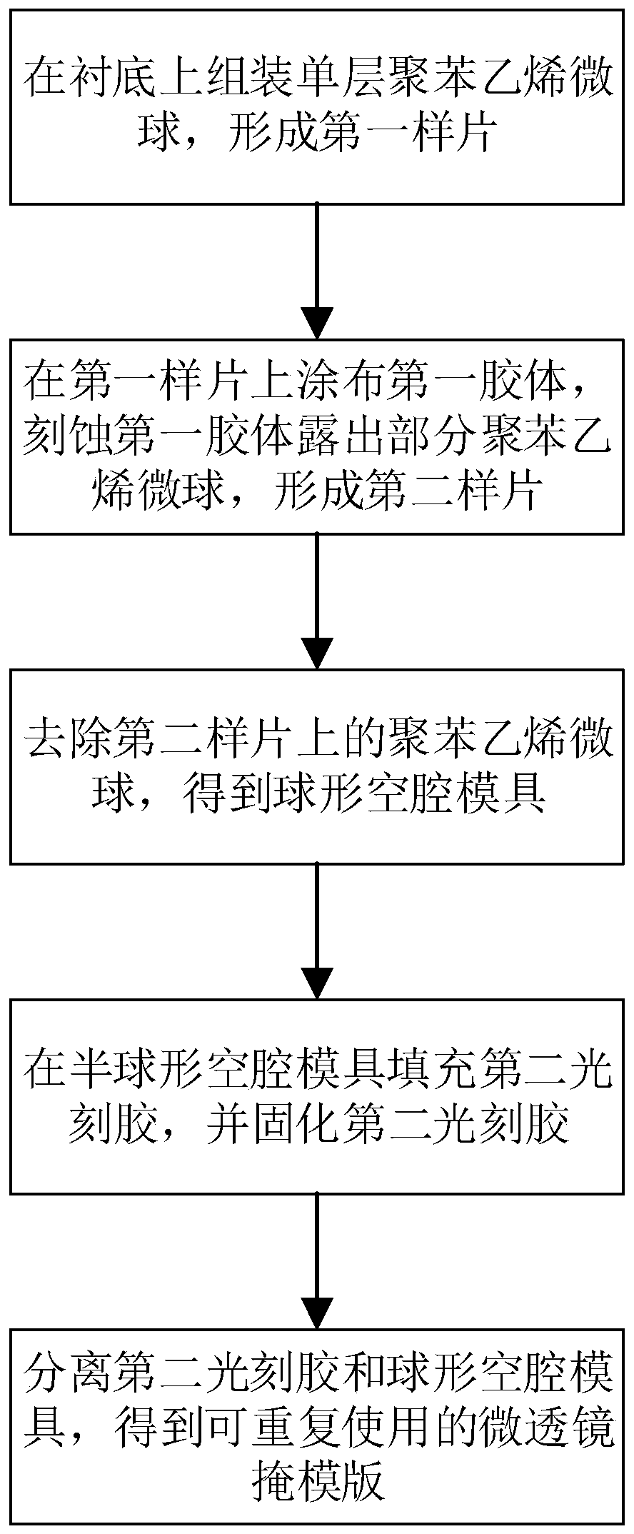
[0046] Such as figure 1 Shown, in embodiment 1, a kind of microlens reticle preparation method specifically comprises the following steps:

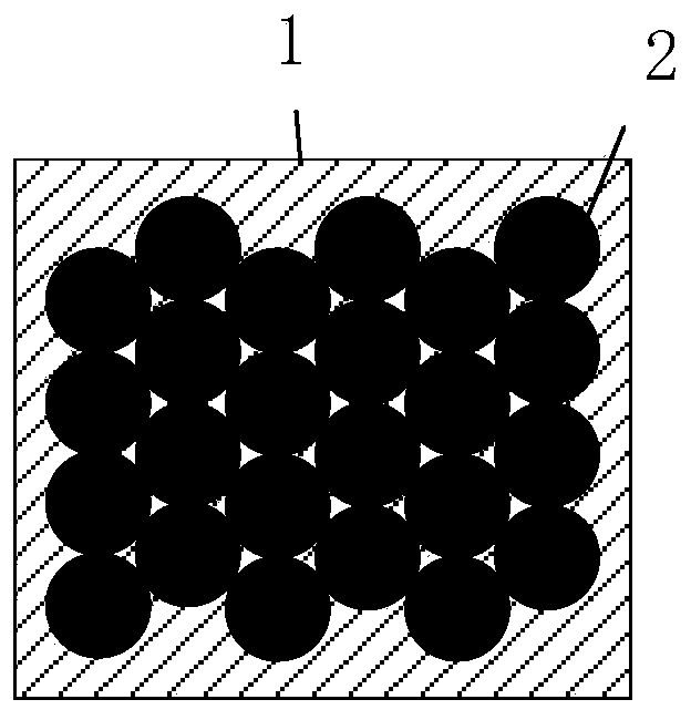
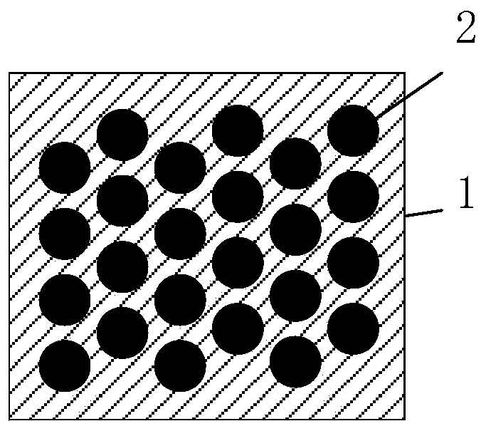
[0047] S01: Assemble a single-layer polystyrene microsphere 2 array on a substrate 1 to form a first sample; specifically, as figure 2As shown, prepare a clean and dry silicon substrate 1 substrate, use 5% w / v polystyrene microspheres with a diameter of 600nm 25ml, add 0.4ml of absolute ethanol, and assemble the closely arranged The polystyrene microsphere 2 array is assembled on the silicon substrate 1, and the size of the polystyrene microsphere 2 can be changed according to the size of the microlens reticle 8 to be prepared, and a single-layer polystyrene microsphere is assembled on the silicon substrate 1. Ethylene microsphere 2 array effects such as figure 2 shown. Further, the RIE etching method is used to etch the polystyrene microsphere 2 array to reduce the diameter of the polystyrene microsphere 2, so that the closely arran...

Embodiment 2

[0053] This embodiment has the same inventive concept as Embodiment 1. In Embodiment 2, a method for preparing a microlens reticle specifically includes the following steps:

[0054] S11: Assemble a single-layer polystyrene microsphere 2 array on a substrate 1 to form a first sample; specifically, prepare a clean and dry silicon substrate 1 substrate, using 5% w / v polystyrene microspheres with a diameter of 600 nm Add 0.4ml of absolute ethanol to 25ml of ethylene microspheres, and assemble the closely arranged array of polystyrene microspheres 2 on the silicon substrate 1 by the gas-liquid surface assembly method. It should be understood that the single assembly on the substrate 1 The method of layering the polystyrene microsphere 2 array includes but not limited to the air-liquid surface assembly method, and can also be other assembly methods, such as the spin coating method, and the size of the polystyrene microsphere 2 can be based on the microlens mask to be prepared 8 siz...

Embodiment 3

[0061] This embodiment provides a microlens reticle, specifically, as figure 2 As shown, the microlens reticle 8 includes a substrate 82 and several first microlenses 81 with spherical surfaces, and the first microlenses 81 and the substrate 82 are integrally formed.

[0062] Furthermore, both the first microlens 81 and the substrate 82 of the microlens reticle 8 are made of highly transparent polymers, such as highly transparent polymer PMMA photoresist, and inorganic transparent material silica. Wherein, since the microlens reticle 8 is prepared by the fluidity of a highly transparent polymer, the first microlens on the microlens reticle 8 can concentrate the incident light rays, so that when using the microlens mask When the template 8 is exposed, each light beam converges with higher energy and smaller spot size, thus obtaining a photolithographic effect with high resolution and good uniformity.

[0063] Furthermore, the present invention utilizes the fluidity of highly ...


PUM

PropertyMeasurementUnit
diameteraaaaaaaaaa
diameteraaaaaaaaaa

Abstract

The invention discloses a micro lens mask and a preparation method thereof, which belong to the technical field of nanophotonic devices. The method includes the following steps: assembling a single layer of polystyrene microspheres on a substrate to form a first sample; coating the first sample with a first colloid, and etching the first colloid to expose part of the polystyrene microspheres to form a second sample; removing the polystyrene microspheres on the second sample to obtain a spherical cavity mould; filling the spherical cavity mould with second photoresist, and solidifying the second photoresist by setting and exposing; and separating the second photoresist from the spherical cavity mould to obtain a reusable micro lens mask. The micro lens mask prepared by the invention can beused repeatedly in large-area assisted photolithography of micro-nano patterns, and has the advantages of low cost, short cycle and high efficiency.

Description

technical field [0001] The invention relates to the technical field of nanophotonic devices, in particular to a microlens reticle and a preparation method thereof. Background technique [0002] Under the development and application requirements of today's highly integrated chips and plasma-based physical functional devices, the rapid preparation of large-area micro-nano-scale feature size structural patterns and arrays has become a hot focus. Various micro-nano processes developed in recent years, such as electron and ion beam lithography, double / multi-beam interference lithography, near-field probe scanning lithography and nanoimprinting, have brought huge economic benefits to the society. At the same time, it has also made great contributions to the promotion of scientific and technological development. [0003] The traditional ultraviolet laser double / multi-beam interference lithography method shows the advantages of low cost and high efficiency in the preparation of mic...

Claims


Application Information

Patent Timeline
Patent Type & Authority Applications(China)
IPC IPC(8): G03F1/38G02B3/00
CPCG02B3/0018G03F1/38
Inventor 王军崔官豪刘贤超姬春晖苟君
Owner UNIV OF ELECTRONICS SCI & TECH OF CHINA
Why Eureka
Try Eureka