Integrated colored optical 3D biological printing system based on image-forming principle
A technology of printing system and imaging principle, applied in the field of optical 3D bioprinting system, can solve the problems of inability to realize mixed processing of various materials, inability to complete non-uniform mixed system molding, and low one-time use rate of material liquid, etc.
- Summary
- Abstract
- Description
- Claims
- Application Information
AI Technical Summary
Problems solved by technology
Method used
Image
Examples
Embodiment 1
[0168] Example 1: Fast Batch Printing for 8-Color Microcubes
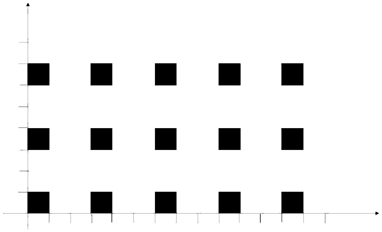
[0169] Bio-ink configuration: 1) 75 mg o-nitrobenzyl-modified hyaluronic acid (HA-NB), 250 mg methacrylic anhydride-modified gelatin (GelMA) and 10 mg phenyl (2,4,6-trimethyl Lithium benzoyl) phosphate (LAP) was dissolved in 10ml deionized water to prepare a light-controlled 3D printing ink containing 0.75% HA-NB, 2.5% GelMA and 0.1% LAP.
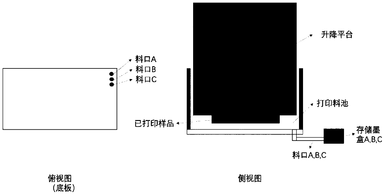
[0170] The structure of the printing device is as figure 1 As shown, the top view is on the left, and the three-dimensional view is on the right. There are 3 outlets A, B, and C, which respectively discharge different inks. The lifting platform is located above the printing pool, and the light is projected into the printing pool from below. When printing different materials Different inks can be conveniently removed, and the type of ink can be easily replaced without causing pollution between inks. Make the printed material more accurate. The type of ink is different, and ...
Embodiment 2
[0183] Example 2: 3D printed cartilage scaffold for osteochondral defect repair
[0184] For example Figure 8 , 9 As shown in 10 and 10, the target structure to be printed is firstly modeled, and then program control is implemented according to the established model to perform "color" volume imaging printing of different materials in different parts of the stent.
[0185] For example, the model built Figure 8 , 9 and 10, Figure 8 It is a cartilage scaffold model, which consists of two parts, namely Figure 9 the upper bracket and Figure 10 the lower bracket. Among them, the upper bracket has 30 round holes in the top view, and there are also 30 round holes on the side, and each round hole intersects.
[0186] Taking the above layer structure as an example, the cutting method of the model in this scheme is as follows Figure 11 shown. The image is cut along the center point 105, and the digital information is input into the image processing system. The cutting p...
PUM
 Abstract
Description
Claims
Application Information
 - R&D
- Intellectual Property
- Life Sciences
- Materials
- Tech Scout
- Unparalleled Data Quality
- Higher Quality Content
- 60% Fewer Hallucinations
Browse by: Latest US Patents, China's latest patents, Technical Efficacy Thesaurus, Application Domain, Technology Topic, Popular Technical Reports.
© 2025 PatSnap. All rights reserved.Legal|Privacy policy|Modern Slavery Act Transparency Statement|Sitemap|About US| Contact US: help@patsnap.com


