Device for waste heat recovery and smoke moisture removal combined wastewater treatment

A technology for waste water treatment and waste heat recovery, which is applied in the direction of heating water/sewage treatment, gaseous waste water treatment, waste gas exhaust device, etc. Increase the dust content of the air, increase the heating area, and realize the effect of cascade utilization

Pending Publication Date: 2019-11-05
CHINA HUADIAN ENG +1
View PDF0 Cites 1 Cited by
  • Summary
  • Abstract
  • Description
  • Claims
  • Application Information

AI Technical Summary

Problems solved by technology

The use of steam evaporation can produce recyclable salt and realize the reuse of water in wastewater. The disadvantage is that it is difficult to recycle low-grade salt. The evaporation process requires high-quality steam, which requires high energy consumption, large investment, and high operating requirements.
The flue gas waste heat evaporation scheme has lower investment, lower operating costs, and improved downstream dust removal efficiency. The disadvantage is that it consumes high-quality flue gas waste heat, affects the flue gas temperature of the air preheater, leads to a decrease in unit efficiency, and increases the load on dust removal equipment. , if no concentration reduction is carried out, a large amount of water will enter the desulfurization system, resulting in a decrease in the evaporation of the desulfurization tower, affecting the amount of desulfurization flushing water, and the amount of treated wastewater will also be limited by the flue gas temperature and load
[0004] Due to the above-mentioned waste of energy and water resources and high investment cost in the conventional whitening technology at present, the elimination of wet plume has the problem that only investment has no profit. The desulfurization wastewater concentration technology consumes high-quality heat energy, and has high energy consumption, high investment cost, and operational requirements. High, adverse effects on unit efficiency and other issues

Method used


Image

  • Device for waste heat recovery and smoke moisture removal combined wastewater treatment
  • Device for waste heat recovery and smoke moisture removal combined wastewater treatment
  • Device for waste heat recovery and smoke moisture removal combined wastewater treatment

Examples


Embodiment 1

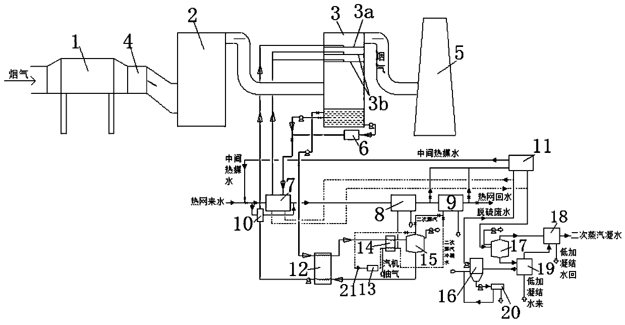
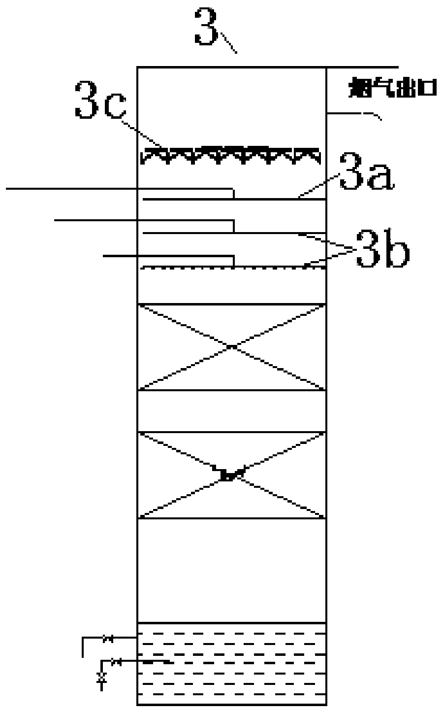
[0042] This embodiment provides a device for waste heat recovery and whitening combined with waste water treatment, such as figure 1 , 2 , 3 and 4, the absorption heat pump system includes a dust removal unit 1, an economizer 4, a desulfurization unit 2, an absorption unit 3, and a chimney 5 connected in sequence, and also includes a first circulation loop and is arranged on the first circulation loop The first heat exchanger 7, the liquid inlet end of the first circulation loop is communicated with the bottom of the absorption unit 3, and the liquid outlet is communicated with the upper part of the absorption unit 3; in this embodiment, the dust removal unit 1 is an electric dust collector, saving The coal device 4 is a low-temperature economizer, and the desulfurization unit 2 is a desulfurization tower; the absorption unit 3 can be an absorption tower, and the absorption tower can be an empty tower or a packed tower, and when it is a packed tower, the packing can be single-...

Embodiment 2

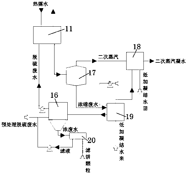
[0060] This embodiment provides a device for waste heat recovery and whitening combined with waste water treatment. On the basis of the above embodiment 1, it also includes a condenser 18, which communicates with the secondary steam outlet on the upper part of the waste water flash tank 17. The condenser 18 also Communicated with the waste water cooler 19, so that the heat exchange medium from the raised temperature in the waste water cooler 19 enters the condenser 18, and exchanges heat again with the secondary steam from the waste water flash tank 17;

[0061] Further, it also includes a second heat exchanger 8 and a third heat exchanger 9 connected in sequence, and the second heat exchanger 8 is also connected with the first heat exchanger 7, so that the incoming water from the heating network passes through the first heat exchanger in sequence. 7, the second heat exchanger 8 and the third heat exchanger 9 to form the return water of the heat network; the second heat exchang...

Embodiment 3

[0065] This embodiment provides a device for waste heat recovery and whitening combined with waste water treatment. On the basis of the above-mentioned embodiment 1 or 2, it also includes a first pump, which communicates with the waste water flash tank 17, and is used to make the waste water flash tank 17 It is in a negative pressure state and controls its internal vacuum degree; that is, in order to ensure that the heated wastewater can be flashed and concentrated, the low temperature phase change concentration system needs to be equipped with a vacuum pump (that is, the first pump), the vacuum pump and the wastewater flash tank and condensation The condenser is connected in series and located behind the condenser. The secondary steam is cooled in the condenser first. During the cooling process, a phase change occurs to generate a negative pressure, which can maintain the negative pressure of the system itself. However, a vacuum pump is required to start the system and maintain...


PUM


Abstract

The invention discloses a device for waste heat recovery and smoke moisture removal combined wastewater treatment. The device is used for solving the problems of smoke waste heat recovery and wastewater concentration of a power plant, and is composed of an absorption heat pump system, a wastewater concentration system and a press filtration system. The device utilizes the waste heat of smoke of the coal-fired power plant or other industries to concentrate wastewater, the concentrating process has little influence on the humidity of the smoke, the wastewater is turned into usable water, and therecovered heat of the smoke is transmitted into a low-pressure heater system to realize the gradient utilization of the heat energy. The concentrated and reduced high-concentration wastewater can beconveyed into a evaporative drying system, so the heat required for the evaporative drying system is greatly reduced, the influences on units are reduced, and the whole device has the advantages of low energy consumption, low investment and low running cost.

Description

technical field [0001] The invention belongs to the technical field of environmental protection, and specifically relates to a device for waste heat recovery and whitening combined with waste water treatment, in particular to a device for deep recovery of waste heat from flue gas in thermal power plants, elimination of wet smoke plume and water collection, and waste water treatment in conjunction with waste water treatment in other fields. A method and device for deep recovery of gas waste heat, elimination of wet plume, water collection and wastewater treatment. Background technique [0002] At present, the mainstream technology for eliminating wet plume is to arrange the flue gas condenser, spray tower after the desulfurization tower, or add a slurry cooler on the slurry circulation slurry pipe to cool down the flue gas at the outlet of the desulfurization tower to precipitate moisture, and use the original flue gas Waste heat is used to heat the clean flue gas. This type ...

Claims


Application Information

Patent Timeline
Patent Type & Authority Applications(China)
IPC IPC(8): C02F9/10F24D3/18F22D1/00F23J11/00F23J15/00F23J15/04F28B9/04F28D21/00C02F103/18
CPCC02F1/001C02F1/043C02F1/048C02F1/06C02F1/16C02F9/00C02F2001/007C02F2103/18F22D1/00F23J11/00F23J15/006F23J15/04F24D3/18F28B9/04F28D21/0012
Inventor 王争荣沈明忠汪洋胡小夫苏军划夏怀鹏耿宣沈建永李伟王桦
Owner CHINA HUADIAN ENG
Why Eureka
Try Eureka