

High and low frequency ripple current suppression method in electric vehicle in-vehicle single-phase charging system
A charging system and electric vehicle technology, applied in the direction of electric vehicle charging technology, electric vehicles, charging stations, etc., can solve the problem of not considering the high frequency current ripple of the auxiliary battery, so as to suppress the low frequency/secondary ripple current, reduce the The effect of cost and vehicle space, good friendliness
- Summary
- Abstract
- Description
- Claims
- Application Information
AI Technical Summary
Problems solved by technology
Method used
Image

Examples
Embodiment 1
[0033] (1) Topology
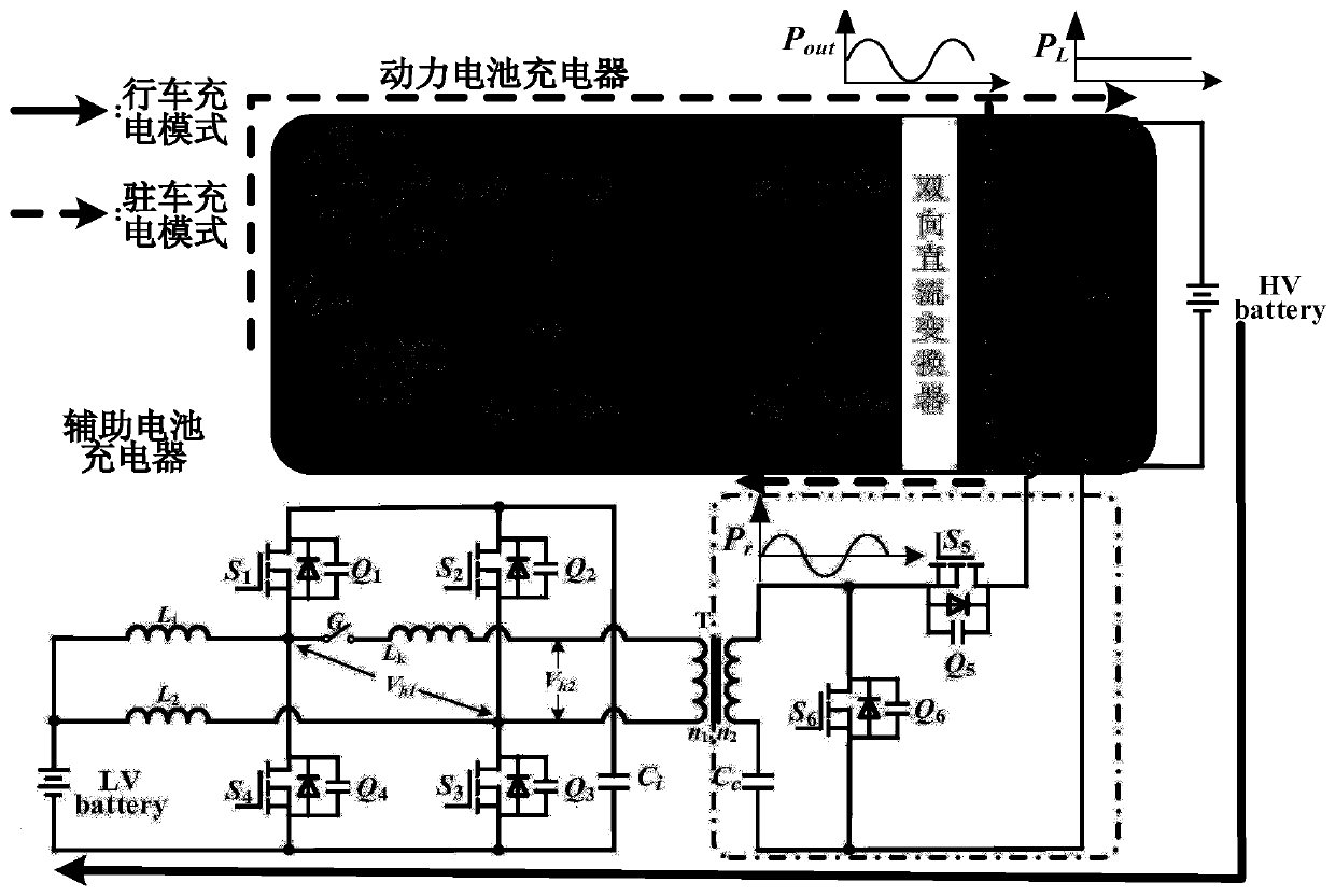
[0034] In the on-board charging system of electric vehicles, by rationally designing the charging topology for the auxiliary battery, the high-frequency ripple current suppression for the auxiliary battery (low-voltage battery) and the low-frequency power battery (high-voltage battery) single-phase PWM rectification charging can be realized. suppression of ripple current. The structure of power and auxiliary battery charging system is as follows: figure 1 shown.
[0035] figure 1 In the above, the power battery charger is composed of a single-phase PWM rectifier and a DC / DC converter. It works in the parking charging mode, and the power flow path is shown by the dotted arrow. The single-phase AC power supply u s One end of the input filter inductor L S One end is connected, the other end is connected to the power switch Q r2 source of the power switch Q r3 The drain is connected; the inductance L S The other end of the power switch Q r1 source of ...
Embodiment 2
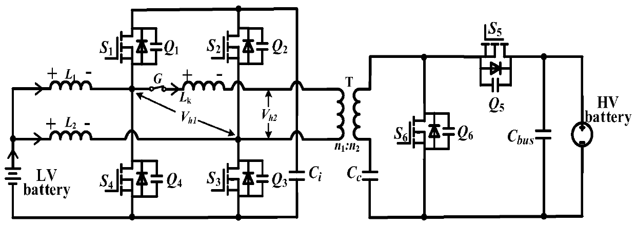
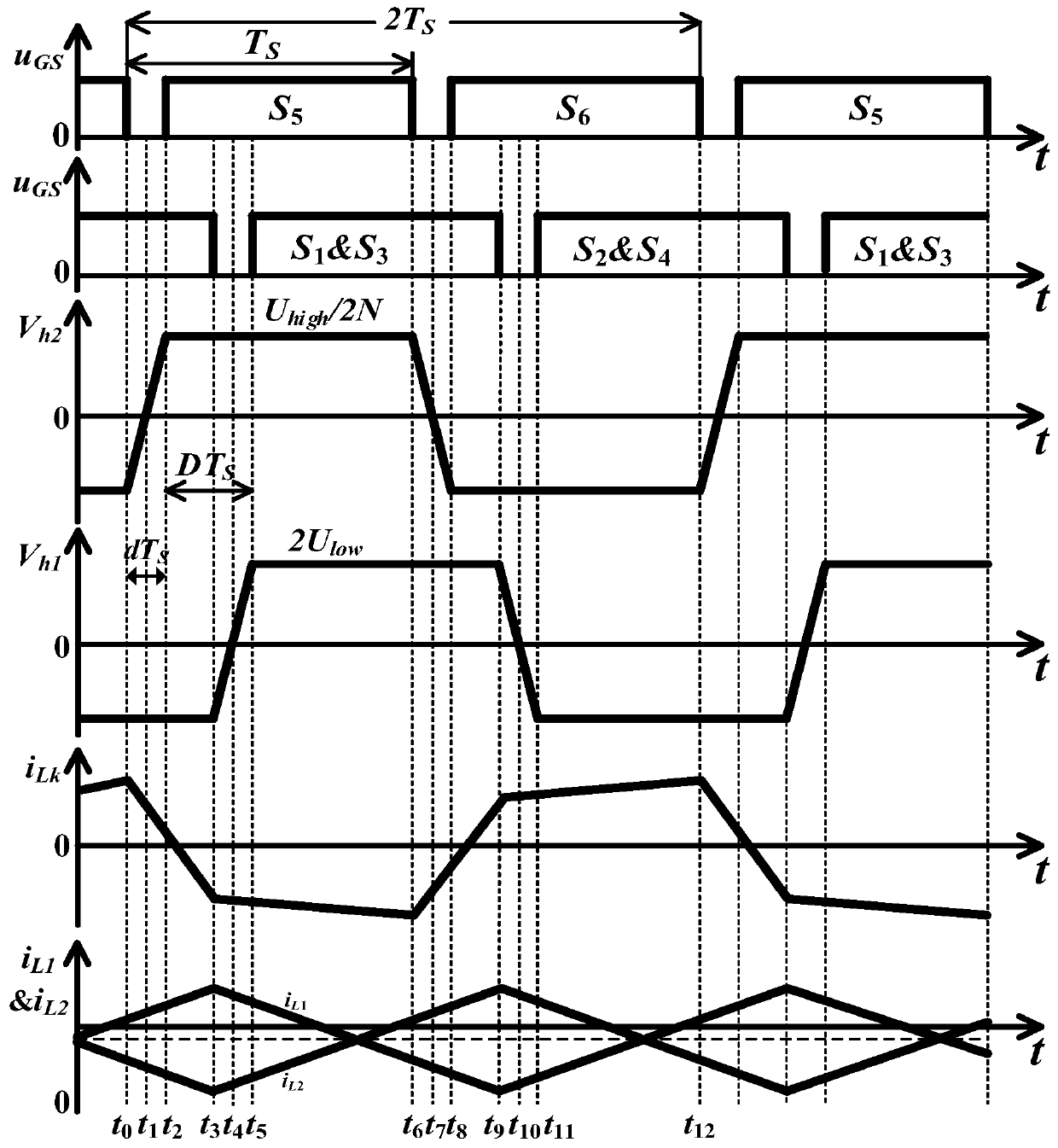
[0068] Below to figure 1 The structure diagram of the power and auxiliary battery charging system in the electric vehicle on-board charging system shown, figure 2 and Figure 4 The topological equivalent circuit diagram of and image 3 and Figure 5 The principle and method of the present invention will be described with respect to the main characteristic waveforms of the topologically stable operation. The following describes the suppression of high-frequency ripple current when the power battery charges the low-voltage auxiliary battery and the suppression of low-frequency ripple current when the power grid performs single-phase PWM rectification and charging on the power battery.
[0069] 1. The principle and method of high-frequency ripple current suppression for auxiliary battery charging during driving
[0070] The duty cycle of the driving signals of all the power switch tubes of the converter is fixed at 0.5, and the power switch Q 1 -Q 6 The driving signal is S...
PUM
 Abstract
Description
Claims
Application Information