
Method for adjusting magnetic anisotropy of magnetic tunnel junction and corresponding magnetic tunnel junction

A technology of magnetic anisotropy and magnetic tunnel junction, which is applied in the fields of magnetic field controlled resistors, components of electromagnetic equipment, manufacturing/processing of electromagnetic devices, etc. Stability issues, reduction of lattice mismatch and interfacial stress, effect of epitaxial preparation and performance

Active Publication Date: 2020-01-17
HUAZHONG UNIV OF SCI & TECH
View PDF1 Cites 3 Cited by
  • Summary
  • Abstract
  • Description
  • Claims
  • Application Information

AI Technical Summary

Problems solved by technology

In particular, high enough perpendicular magnetic anisotropy can be obtained to solve the problem of high write power consumption of spin transfer torque magnetic memory; in addition, this method can also reduce the lattice mismatch at the interface, which helps Epitaxial Fabrication and Performance Improvement of Magnetic Tunnel Junction

Method used


Image

  • Method for adjusting magnetic anisotropy of magnetic tunnel junction and corresponding magnetic tunnel junction
  • Method for adjusting magnetic anisotropy of magnetic tunnel junction and corresponding magnetic tunnel junction
  • Method for adjusting magnetic anisotropy of magnetic tunnel junction and corresponding magnetic tunnel junction

Examples


Embodiment 1

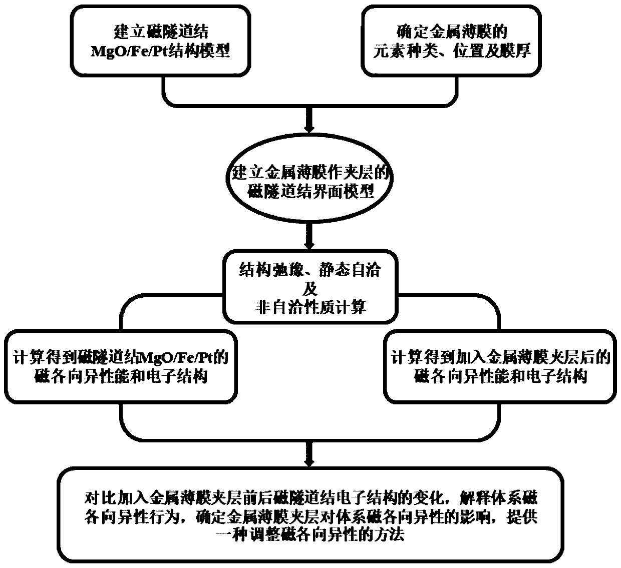
[0047] This embodiment reveals that changing the element type of the metal interlayer can greatly adjust the magnetic anisotropy of the MgO / Fe / Pt magnetic tunnel junction through first-principle calculations.

[0048] The calculation model used in this embodiment is as follows image 3 As shown, along the (001) crystal direction, there are 10nm vacuum layer, 4ML MgO, 1ML metal interlayer, 8ML Fe, 3ML Pt and 10nm vacuum layer. In order to ensure the consistency of the interface structure, bcc-Fe is selected as the standard for interface matching, so that other film layers will be deformed accordingly and the in-plane lattice constant will be fixed at

[0049] Alternative interlayer materials include Group VIII transition metals, silver Ag, and gold Au. The unit cells of Co, Ru, and Os are close-packed hexagonal structures, and it is difficult to find suitable crystal planes to splice with bcc-Fe(001) planes (considering The diversity of ferromagnetic layer materials does not...

Embodiment 2

[0059] In this embodiment, the magnetic properties and electronic structure of metal interlayers added at different positions of MgO / Fe_8ML / Pt are calculated by first principles, so as to obtain the effect of the position of the metal interlayer on the magnetic anisotropy of the magnetic tunnel junction.

[0060] Select 1ML Rh film as a metal interlayer and insert it into MgO / Fe_8ML / Pt, adjust the position and build a model: A.MgO / Rh_1ML / Fe_8ML / Pt, B.MgO / Fe_4ML / Rh_1ML / Fe_4ML / Pt, C.MgO / Fe_8ML / Rh_1ML / Pt, the magnetic anisotropy energy density was calculated, and the results are shown in Table 2.

[0061] Table 2 Magnetic anisotropy energy density obtained by inserting 1ML Rh thin film interlayer at different positions

[0062] Rh film position MgO / Fe interface Inside the ferromagnetic layer Fe / Pt interface MAE (mJ / m 2 )

9.2566 5.1100 -5.6298

[0063] Figure 7 is the calculated differential charge density of the three interface models.

[0064...

Embodiment 3

[0070] In this embodiment, 1-3ML Rh thin film interlayers are added to the MgO / Fe interface of the MgO / Fe_8L / Pt model, and first-principle calculations are performed on the magnetic anisotropy and electronic structure to obtain the thickness of the Rh thin film interlayer. Influence of Magnetic Anisotropy in Magnetic Tunnel Junction.

[0071] Table 3 is the calculated magnetic anisotropy energy density under different Rh film thicknesses. The results show that when the thickness of the Rh film is within a certain range, the magnetic anisotropy of the interface model is positive, and its perpendicular magnetic anisotropy is stronger than that of the MgO / Fe_8L / Pt model without Rh interlayer. Preferably, when 2ML Rh thin film interlayer is added, the magnetic anisotropy can be as high as 9.9921mJ / m 2 .

[0072] Table 3 Magnetic anisotropy energy density at different Rh film thicknesses

[0073] Rh interlayer thickness 1ML 2ML 3ML MAE (mJ / m 2 )

9.2566 ...


PUM


Abstract

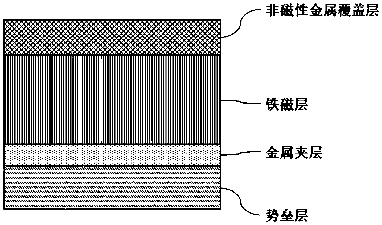
The invention belongs to the field of spintronics application, and discloses a method for adjusting magnetic anisotropy of a magnetic tunnel junction and the corresponding magnetic tunnel junction, the adjusting method is specifically characterized in that a metal interlayer is inserted into a film layer structure of the magnetic tunnel junction to control contribution of an electron orbit coupling effect, so that adjustment of the magnetic anisotropy of the magnetic tunnel junction is realized; an initial film layer structure of the magnetic tunnel junction sequentially comprises a barrier layer, a ferromagnetic layer and a non-magnetic metal covering layer. The method is based on the interface effect, the distribution of the Bloch electronic state near the Fermi level is changed by adding the metal interlayer, so that the contribution of a coupling action item between electron orbits is controlled, the magnetic anisotropy of the magnetic tunnel junction is accurately adjusted (such as atomic magnetic moment and magnetic anisotropy performance, magnetoelectric coefficient and the like of the magnetic tunnel junction), and various requirements in practical application are met. Especially, high enough vertical magnetic anisotropy can be obtained to solve the problem that the writing power consumption of the spin transfer torque magnetic memory is too high.

Description

technical field [0001] The invention belongs to the application field of spintronics, and more specifically relates to a method for adjusting the magnetic anisotropy of a magnetic tunnel junction and a corresponding magnetic tunnel junction. Background technique [0002] As we all know, electrons have two intrinsic properties of charge and spin. Charge determines the behavior of electrons in an electric field, and spin affects the behavior of electrons in a magnetic field. Unlike traditional semiconductor memories that rely on charges to transmit and store data, magnetic random access memory completes the flipping of data states based on electron spin effects. The development of MRAM has gone through two stages: magnetic field drive and current drive. In contrast, the current-driven type, that is, the spin-transfer torque magnetic memory, has no additional write information lines, the structure is simpler, and the switching current decreases with the reduction of the unit s...

Claims


Application Information

Patent Timeline
IPC IPC(8): H01L43/12H01L43/08H01L43/02H01L43/10
CPCH10N50/80H10N50/01H10N50/85H10N50/10
Inventor 程晓敏连晨朱云来缪向水
Owner HUAZHONG UNIV OF SCI & TECH
Learn More