Method and system for obtaining rotor position of a motor
A motor rotor and acquisition method technology, applied in control system, motor control, motor parameter estimation/correction, etc., can solve problems such as large error and difficult control, reduce cost, improve reliability, and improve decoding accuracy Effect
- Summary
- Abstract
- Description
- Claims
- Application Information
AI Technical Summary
Problems solved by technology
Method used
Image
Examples
Embodiment 1
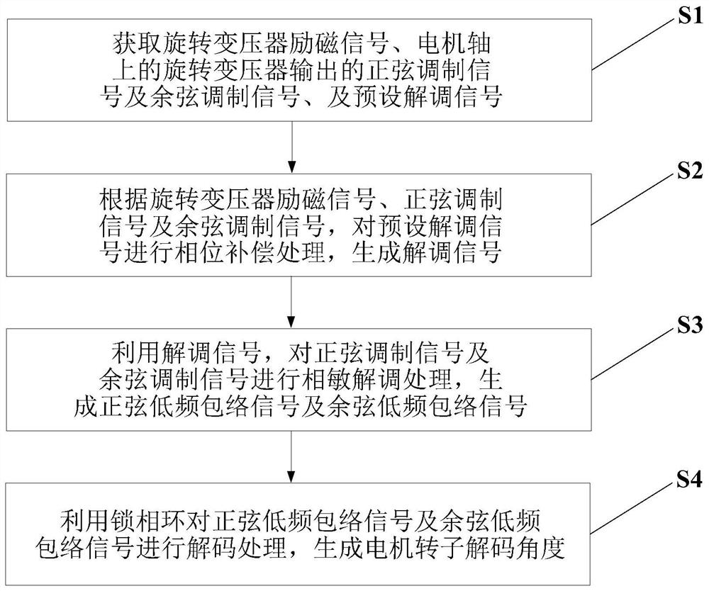
[0045] This embodiment provides a motor rotor position acquisition method, which is applied in the field of motor control, such as figure 1 shown, including the following steps:
[0046] Step S1: Obtain the excitation signal of the resolver, the sine modulation signal and the cosine modulation signal output by the resolver on the motor shaft, and the preset demodulation signal.
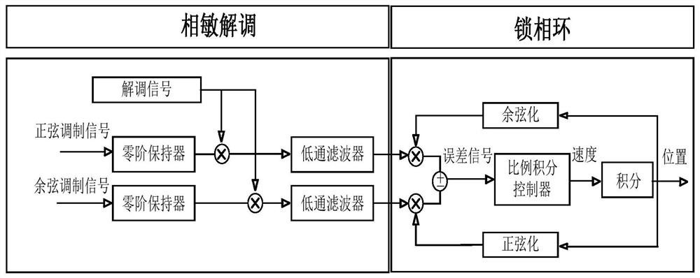
[0047] The output voltage of the resolver will change with the rotor angle, so in the motor control system, it is often used to obtain the rotor position of the motor. When an AC high-frequency voltage of a certain frequency is applied to the excitation winding of the resolver, the voltage amplitude of the output winding has a sine or cosine function relationship with the rotor rotation angle, or maintains a certain proportional relationship, or is linear with the rotation angle within a certain range of rotation angle. relation. The embodiment of the present invention uses the sine modulation signa...
Embodiment 2
[0137] This embodiment provides a motor rotor position acquisition system, such as Figure 24 shown, including:
[0138] The signal acquisition module 1 is used to acquire the resolver excitation signal, the sine modulation signal and cosine modulation signal output by the motor shaft resolver, and the preset demodulation signal; this module executes the method described in step S1 in Embodiment 1, and This will not be repeated here.
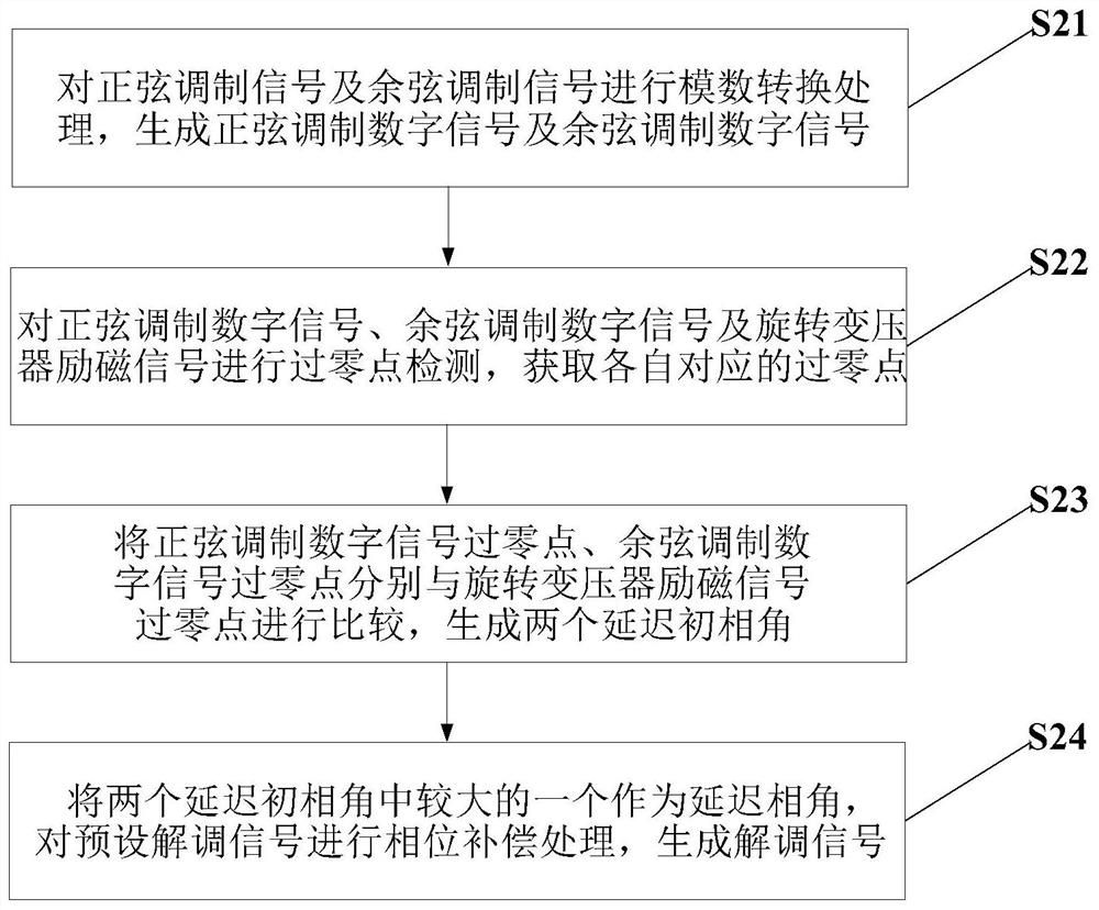
[0139] The demodulation signal generation module 2 is used to perform phase compensation processing on the preset demodulation signal according to the resolver excitation signal, the sine modulation signal and the cosine modulation signal to generate the demodulation signal; this module executes the step S2 in the embodiment 1. The method described will not be repeated here.
[0140] The envelope signal generating module 3 is used to utilize the demodulation signal to carry out phase-sensitive demodulation processing on the sine modulation sig...
Embodiment 3
[0144] An embodiment of the present invention provides a computer device, such as Figure 25 As shown, it includes: at least one processor 401 , such as a CPU (Central Processing Unit, central processing unit), at least one communication interface 403 , memory 404 , and at least one communication bus 402 . Wherein, the communication bus 402 is used to realize connection and communication between these components. Wherein, the communication interface 403 may include a display screen (Display) and a keyboard (Keyboard), and the optional communication interface 403 may also include a standard wired interface and a wireless interface. The memory 404 may be a high-speed RAM memory (Ramdom Access Memory, volatile random access memory), or a non-volatile memory (non-volatile memory), such as at least one disk memory. Optionally, the memory 404 may also be at least one storage device located away from the aforementioned processor 401 . Wherein, the processor 401 can execute the meth...
PUM
 Abstract
Description
Claims
Application Information
 - R&D
- Intellectual Property
- Life Sciences
- Materials
- Tech Scout
- Unparalleled Data Quality
- Higher Quality Content
- 60% Fewer Hallucinations
Browse by: Latest US Patents, China's latest patents, Technical Efficacy Thesaurus, Application Domain, Technology Topic, Popular Technical Reports.
© 2025 PatSnap. All rights reserved.Legal|Privacy policy|Modern Slavery Act Transparency Statement|Sitemap|About US| Contact US: help@patsnap.com


