Sludge drying tail gas treatment system and method

A technology for sludge drying and tail gas treatment, which is applied in water/sludge/sewage treatment, dehydration/drying/thickened sludge treatment, water/sewage treatment, etc. Sludge drying tail gas treatment effect is limited and other problems, to achieve the effect of saving equipment maintenance workload, saving equipment footprint, and will not produce secondary pollution

Active Publication Date: 2020-04-17
HUNAN JUNXIN ENVIRONMENTAL PROTECTION CO LTD
View PDF9 Cites 2 Cited by
  • Summary
  • Abstract
  • Description
  • Claims
  • Application Information

AI Technical Summary

Problems solved by technology

This type of method has the disadvantages of low treatment load, single type of pollutants, unstable treatment effect, large floor area, and inconvenient maintenance. More importantly, the circulating wastewater generated during the tail gas treatment needs additional treatment, and there are secondary contamination defect
[0006] (2) Deodorization technologies such as UV and catalytic oxidation can also be applied to sludge drying tail gas treatment, but these methods have limited effects on sludge drying tail gas treatment, and it is difficult to remove high-concentration, complex and fluctuating pollutants. Sludge drying tail gas treatment until the emission reaches the standard
[0007] It is worth noting that in the existing sludge drying tail gas treatment technology, spray towers and biological deodorization boxes are mainly used to cool and deodorize the tail gas, and the complete biochemical degradation of the pollutants in the tail gas has not been achieved. At the same time, the facilities Occupies a large area and is inconvenient to maintain

Method used


Image

  • Sludge drying tail gas treatment system and method
  • Sludge drying tail gas treatment system and method

Examples


Embodiment Construction

[0045] The present invention will be further described below in conjunction with the accompanying drawings and specific preferred embodiments, but the protection scope of the present invention is not limited thereby.

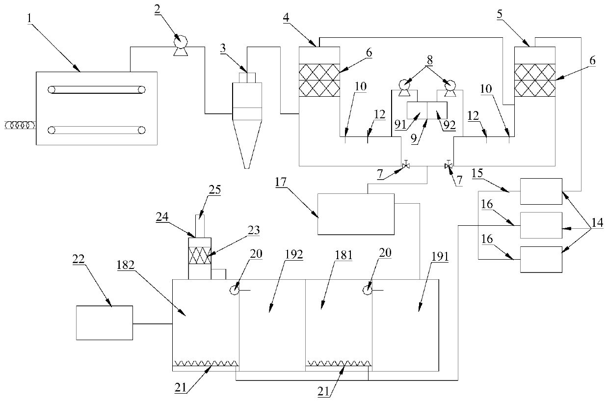
[0046] like figure 1 As shown, a sludge drying tail gas treatment system of the present invention includes: a sludge drying machine 1, an induced draft fan 2, a cyclone separator 3, an acidic spray tower 4, an alkaline spray tower 5, a blower 14, Sewage storage tank 17, nitrification tank, denitrification tank and activated carbon absorption tower 23; mud dryer 1, induced draft fan 2, cyclone separator 3, acid spray tower 4, alkaline spray tower 5 are connected in sequence; acid spray The tower 4 and the alkaline spray tower 5 are respectively connected with the sewage storage tank 17; the alkaline spray tower 5 is connected with the nitrification tank through the air blower 14; the sewage storage tank 17, the denitrification tank, the nitrification tank, and th...


PUM


Abstract

The invention discloses a sludge drying tail gas treatment system and a sludge drying tail gas treatment method. The sludge drying tail gas treatment system comprises a sludge drying machine, an induced draft fan, a cyclone separator, a spray tower, an air blower, a sewage storage tank, a nitrification tank, a denitrification tank and an activated carbon absorption tower, wherein the sludge dryingmachine, the induced draft fan, the cyclone separator and the spray tower are sequentially connected in series; the spray tower is communicated with the nitrification tank through the air blower; thesewage storage tank, the denitrification tank, the nitrification tank and the activated carbon absorption tower are sequentially connected in series. The invention also correspondingly provides the sludge drying tail gas treatment method. The method comprises the following steps: carrying out chemical oxidation treatment on the tail gas, carrying out biochemical degradation, performing adsorbingwith activated carbon, and conducting discharging. According to the invention, the technical effects of treating the waste with the waste and cooperatively treating tail gas and waste water are finally achieved, up-to-standard discharge of sludge drying tail gas and waste water is realized, energy conservation and environmental protection are realized, secondary pollution is not generated, and meanwhile, the method also has the advantages of decreasing equipment occupied area and equipment maintenance workload and reducing equipment comprehensive operation cost.

Description

technical field [0001] The invention relates to the technical field of environmental protection, in particular to a treatment system and treatment method applicable to sludge drying tail gas. Background technique [0002] Sludge drying is an important technical means to achieve sludge reduction and subsequent treatment. The treatment methods of sludge drying can be divided into direct contact heat drying and indirect non-contact heat drying. The heat source used in sludge drying It mainly includes solar energy, electric energy, methane gas, steam, waste heat, etc. Direct contact heat drying treatment means direct contact between sludge and heat medium. Because of its high heat transfer efficiency and heat energy utilization rate, it is more commonly used in sludge drying technology. [0003] The sludge anaerobic digestion technology recovers the carbon energy in the sludge and converts it into methane gas to recover the energy in the sludge; Mud reduction and heat recyclin...

Claims


Application Information

Patent Timeline
Patent Type & Authority Applications(China)
IPC IPC(8): B01D53/75B01D53/78B01D53/84B01D53/04B01D45/12C02F11/13C02F9/14
CPCB01D53/75B01D53/78B01D53/84B01D53/04B01D45/12C02F11/13C02F9/00B01D2253/102C02F1/444Y02E50/30
Inventor 刘晓峰张浩王勇
Owner HUNAN JUNXIN ENVIRONMENTAL PROTECTION CO LTD
Why Eureka
Try Eureka