Cladding layer of valve sealing surface

A valve sealing and cladding layer technology, which is applied in the coating, metal material coating process, etc., can solve problems affecting the application of laser technology, and achieve the effects of large-scale production, high hardness, and significant economic benefits

Inactive Publication Date: 2020-04-21
河北瑞驰伟业科技有限公司
View PDF6 Cites 1 Cited by
  • Summary
  • Abstract
  • Description
  • Claims
  • Application Information

AI Technical Summary

Problems solved by technology

However, at present, there is almost no special metal powder for laser cladding in the domestic and foreign markets. Although some progress has been made in preparing the powder required for laser cladding by mechanical powder mixing, there are still many problems, which affect the application of laser technology on the sealing surface of valves.

Method used


Image

  • Cladding layer of valve sealing surface
  • Cladding layer of valve sealing surface
  • Cladding layer of valve sealing surface

Examples


Embodiment 1

[0032] This embodiment relates to the cladding layer of the valve sealing surface.

[0033] A cladding layer of a valve sealing surface, the alloy powder of the cladding layer includes the following raw material components in mass percentage:

[0034] Carbon 1.1~2.0%, Chromium 19.5~20.0%, Nickel 3.6~4.0%, Molybdenum 1.0~1.4%, Boron 2.0%, Silicon 3.0%, Tungsten 1.5~2.0%, Vanadium 0.51~0.6%, Lanthanum≤0.05%, Yu The amount is iron.

[0035] The raw material formula of alloy powder in each embodiment is as shown in the table below:

[0036] Example 1.1 Example 1.2 Example 1.3 carbon 78g 87.5g 140g chromium 1365g 1397g 1395g nickel 252g 267.5g 280g molybdenum 70g 90g 98g boron 140g 140g 140g silicon 210g 210g 210g tungsten 105g 124g 140g vanadium 36g 36g 42g lanthanum 3.5g 3.5g 3.5g iron 4740.5g 4644.5g 4551.5g

[0037] The preparation method of each embodiment alloy powder in the ...

Embodiment 2

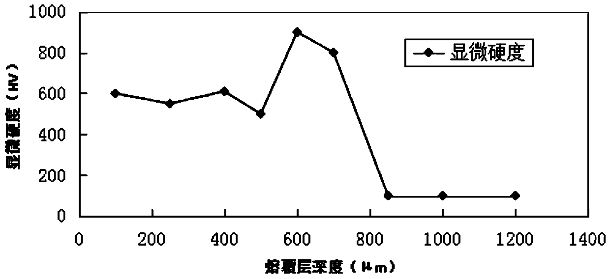
[0047] This embodiment relates to the detection of the performance of the cladding layer on the sealing surface of the valve in the first embodiment.

[0048] The alloy powder of Example 1.1 is compared with the cladding layer prepared by the laser cladding process of the present invention with the cladding layer prepared by the plasma spray welding process of the same alloy powder. The structure and phase, the thickness and quality of the dissolved layer, the composition and dilution rate of the dissolved layer, the hardness of the dissolved layer, the wear resistance of the dissolved layer and the corrosion resistance of the dissolved layer were tested. The test results are as follows:

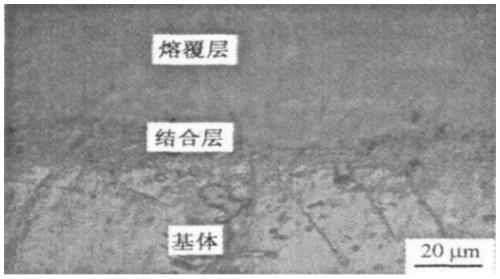
[0049] (1) Detection of the combination of the solution layer and the matrix

[0050] Analyzing the metallographic structure of the molten layer treated by laser cladding and plasma spray welding process see figure 2 , along the vertical direction of the processing surface, it can be divid...


PUM

PropertyMeasurementUnit
Surface roughnessaaaaaaaaaa

Abstract

The invention discloses a cladding layer of a valve sealing surface. The alloy powder of the cladding layer comprises iron, chromium, nickel, molybdenum, boron, silicon, carbon, tungsten and vanadiumelements, wherein the iron is used as a main body, the content of the iron is more than 50%, the content of the chromium is more than 15%, the content of the boron is 2.0%, and the content of the silicon is 2.0%; the preparation technological process of the alloy powder comprises the steps of burdening, smelting, atomizing, drying and screening; and the cladding method of the cladding layer adoptsa laser cladding process, cladding lap joint is carried out on the valve sealing surface, and the thickness of the cladding layer is 1000-2000 microns. According to the obtained cladding layer, cobalt-free alloy with iron and chromium as main bodies is utilized, the wear resistance, the impact resistance, the corrosion resistance and the like of the sealing surface of the ball valve are more excellent through a specific alloy powder preparation process and a cladding method of the cladding layer, the quality of the valve sealing surface is improved, and the service life of the valve is prolonged.

Description

technical field [0001] The invention relates to the technical field of surface engineering, in particular to a cladding layer of a valve sealing surface. Background technique [0002] The valve is a control part in the fluid delivery system, and the valve sealing surface refers to the part where the valve seat and the closing member contact each other to form a seal. During the use of the valve, the sealing surface is in the medium for a long time and is eroded and corroded by the medium. It is the most critical working surface of the valve, and its quality is related to the service life of the valve. The surfacing materials of existing valve sealing surfaces are cobalt-containing alloys such as Stellite6 and cobalt-free materials such as 410, 440C, and 616. Due to the high price of cobalt-based alloys and the lack of cobalt resources in my country, cobalt-based alloys are used in valve sealing surface materials. Restricted; 410 cobalt-free materials are not suitable for use...

Claims


Application Information

Patent Timeline
IPC IPC(8): C23C24/10C22C38/02C22C38/44C22C38/46C22C38/54
CPCC22C38/005C22C38/02C22C38/44C22C38/46C22C38/54C23C24/103
Inventor 王菊花李建平孙艳敏张永超
Owner 河北瑞驰伟业科技有限公司
Why Eureka
Try Eureka