Plate type PECVD system integrated with anti-PID device and passivation film-coating method

A passivation film and plate technology, applied in gaseous chemical plating, coating, photovoltaic power generation, etc., can solve the problems of carrier life reduction, phosphorus redistribution, metal impurities, graphite boat and furnace tube damage, and poor compactness. To achieve the effect of shortening the passivation coating time, reducing the risk of bending, and avoiding thermal shock

Inactive Publication Date: 2020-05-29
JA SOLAR TECH YANGZHOU
View PDF6 Cites 1 Cited by
  • Summary
  • Abstract
  • Description
  • Claims
  • Application Information

AI Technical Summary

Problems solved by technology

[0003] There are three ways to prepare the silicon dioxide layer: one is to use PECVD technology, for N 2 O / SiH 4 The silicon dioxide layer is deposited by ionization, but the density of the silicon dioxide layer in this technology is poor, which will seriously damage the graphite boat and the furnace tube, and will also reduce the conversion efficiency of the battery; the second is to add an ozone oxidation device to the PSG removal equipment , to oxidize the surface of the silicon wafer to form a silicon dioxide layer. This technology is low in cost and simple in process; the third is to deposit silicon dioxide by thermal oxygen method. The effect of thermal oxygen deposition of silicon dioxide film is better, but generally requires Under high temperature (600°C-1100°C) for 30min-60min, such long-term high-temperature treatment will cause problems such as reduction of minority carrier life, redistribution of phosphorus, diffusion of metal impurities, etc., which will affect the conversion of solar cells efficiency
At the same time, the current market requires cells to have anti-PID performance. Now the common practice is to use a separate anti-PID machine to deposit an oxide layer after etching. A separate anti-PID device will not only increase the cost of battery manufacturing, but also It will also reduce the production efficiency of cells, and the independent anti-PID equipment completes the passivation chamber (SiO 2 ) after deposition, it is difficult to avoid contact with air again, and contact with air again, it is easy to absorb moisture in the air and reduce the quality of the film

Method used


Image

  • Plate type PECVD system integrated with anti-PID device and passivation film-coating method
  • Plate type PECVD system integrated with anti-PID device and passivation film-coating method
  • Plate type PECVD system integrated with anti-PID device and passivation film-coating method

Examples


Embodiment 1

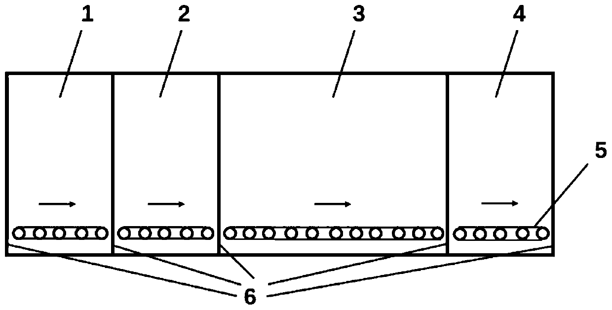
[0035] An embodiment of the present invention discloses a plate type PECVD system integrating an anti-PID device, such as Figure 1-3 As shown, along the direction of material transport, it includes a feed bin 1 , an anti-PID device 2 for depositing a passivation film, a PECVD process bin 3 and an outlet bin 4 .

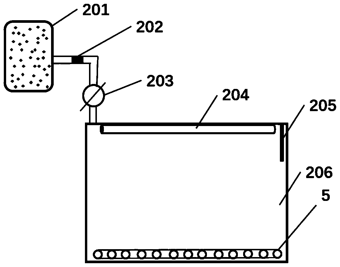
[0036] An anti-PID device is included to provide O 2 Gas cylinder 201, used to induce O 2 produce O 3 The induction device and passivation chamber 206. The induction device is set in the passivation chamber, which can induce O 2 produce O 3 .

[0037] The gas cylinder 201 and the passivation bin 206 are connected by pipelines, and the feeding bin 1 , the passivation bin 206 , the PECVD process bin 3 and the output bin 4 are all equipped with a transmission device 5 .

[0038] During implementation, the material first enters the feed bin 1, and then enters the passivation bin 206 of the anti-PID device, and the O in the gas cylinder 2 Under the induction of the...

Embodiment 2

[0055] Another embodiment of the present invention discloses a passivation coating method. The passivation coating method of this embodiment adopts the plate type PECVD system integrated anti-PID device of embodiment 1, including the following steps:

[0056] Step 1: Silicon wafers enter the feeding bin for the first preheating, preheating to 300-450°C;

[0057] Step 2: The preheated material enters the passivation bin;

[0058] Step 3: Introduce oxygen into the passivation chamber, turn on the UV lamp, and form SiO on the surface of the silicon wafer 2 passivation film;

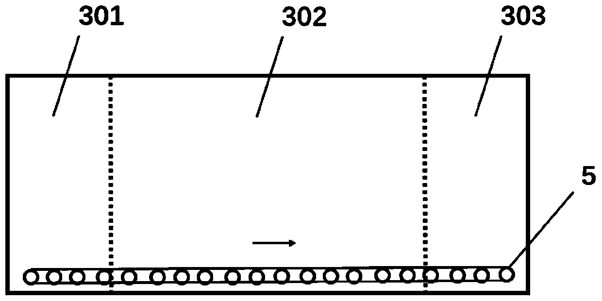
[0059] Step 4: SiO formation on the surface 2 The silicon wafer with passivation film enters the PECVD process chamber, and the material is preheated for the second time in the heating zone to 300-450°C;

[0060] Step 5: The silicon wafer that has been preheated for the second time passes through the film forming process zone and the cooling zone in sequence.

[0061] Step 6: Silicon wafers enter the dis...

Embodiment 3

[0066] This embodiment discloses an improved passivation coating method, which specifically includes the following steps:

[0067] Step 1: After the silicon wafer goes through the wet etching process, the front door 6 of the feeding bin 1 is opened, the silicon wafer is placed on the graphite frame, and the graphite frame enters the feeding bin 1 through the transmission device 5, and the front end of the feeding bin 1 The warehouse door 6 is closed;

[0068] Step 2: Vacuumize the feeding bin, and at the same time, the infrared heater in the feeding bin preheats the silicon wafer in the first step, and controls the temperature of the silicon wafer at 300°C to 450°C;

[0069] Step 3: After preheating, the bin door 6 between the feeding bin 1 and the passivation bin 206 is opened, and the silicon wafer enters the passivation bin 206 in the PID device 2 through the transmission device 5. After the silicon wafer enters, the feeding bin 1 and the chamber door 6 between the passiva...


PUM


Abstract

The invention relates to a plate type PECVD system integrated with an anti-PID device and a passivation film-coating method, and belongs to the technical field of solar cell manufacturing. The problems that the passivation film-coating time is long and the temperature difference between a passivation bin and a PECVD process bin is large in an existing process, and debris is prone to being producedare solved. The plate type PECVD system integrated with the anti-PID device includes a feed bin, the anti-PID device, a PECVD process bin and a discharge bin; the anti-PID device includes a gas bottle, an induction device and a passivation bin; and the induction device can induce O2 to produce O3 at a normal temperature. The passivation film-coating method includes the steps that materials are preheated for the first time, and the materials enter the passivation bin; oxygen is introduced, the induction device is started, and a passivation film is formed on the surface of the materials; the materials is preheated for the second time in a heating area; and the materials pass through a film-forming process area and a cooling area. According to the plate type PECVD system integrated with theanti-PID device and the passivation film-coating method, the SiO2 passivation film is formed at the normal temperature.

Description

technical field [0001] The invention relates to the technical field of solar cell manufacturing, in particular to a plate-type PECVD system integrating an anti-PID device and a passivation coating method. Background technique [0002] At present, the anti-PID technology on the battery side is mainly concentrated on the silicon dioxide / silicon nitride stacking technology. The anti-PID performance of this composite film has been highly recognized by the industry. In the preparation of the silicon dioxide / silicon nitride stack, the silicon dioxide layer is the key point, which directly affects the anti-PID performance of the module, the appearance of the battery and the conversion efficiency. [0003] There are three ways to prepare the silicon dioxide layer: one is to use PECVD technology, for N 2 O / SiH 4 The silicon dioxide layer is deposited by ionization, but the density of the silicon dioxide layer in this technology is poor, which will seriously damage the graphite boat...

Claims


Application Information

Patent Timeline
IPC IPC(8): C23C16/54C23C16/50C23C16/02C23C16/40C23C16/34C23C16/46H01L31/0216H01L31/18
CPCC23C16/0272C23C16/345C23C16/402C23C16/46C23C16/50C23C16/54H01L31/02167H01L31/1868Y02E10/50Y02P70/50
Inventor 于义超陈斌张俊兵
Owner JA SOLAR TECH YANGZHOU
Why Eureka
Try Eureka