
Transition metal complex used as phosphorescent material and application thereof

A technology of transition metals and phosphorescent materials, applied in the directions of luminescent materials, platinum-based organic compounds, palladium organic compounds, etc., can solve the problems of material decomposition, material purity decline, preparation device efficiency and life damage, etc.

Active Publication Date: 2020-06-26
YANTAI XIANHUA OPTOELECTRONICS INST CORP LTD
View PDF5 Cites 0 Cited by
  • Summary
  • Abstract
  • Description
  • Claims
  • Application Information

AI Technical Summary

Problems solved by technology

[0006] The luminescent properties of phosphorescent materials, especially the luminous color and luminous efficiency, are mainly realized by modifying the main ligand, but this modification has a limited range of luminous color tone, and too much modification will lead to the molecular weight of the material being too large. During the purification process, especially the commonly used vacuum sublimation method, the sublimation temperature of the material will increase, and the material will be partially decomposed during the sublimation purification process, resulting in a decrease in the purity of the material, which will play a role in the efficiency and life of the device. lethal damage

Method used


Image

  • Transition metal complex used as phosphorescent material and application thereof
  • Transition metal complex used as phosphorescent material and application thereof
  • Transition metal complex used as phosphorescent material and application thereof

Examples


Embodiment 1

[0056] The synthesis of iridium complex Ir27, reaction equation is as follows:

[0057] (1) Synthesis of chlorine-bridged dimers

[0058]

[0059] (2) Target compound synthesis

[0060]

[0061] Concrete reaction process is as follows:

[0062] (1) Ligand II-A (43.8g, 200mmol), iridium trichloride hydrate (26.7g, 75.7mmol), water 150mL, ethylene glycol methyl ether 400mL, stirred and refluxed under nitrogen atmosphere for 24h; the reaction solution was cooled to room temperature, filtered, rinsed with water, ethanol and acetone in turn, drained and dried naturally to obtain dark green chlorine bridge compound II-A-Cl;

[0063] (2) Add II-A-Cl to the ethylene glycol dimethyl ether solution containing A1, stir the reaction at 80°C for 16h, cool to room temperature, separate the layers, wash the organic phase with water until neutral, and dry over magnesium sulfate. After filtration and concentration under reduced pressure, the residue was purified by column chromatograp...

Embodiment 2

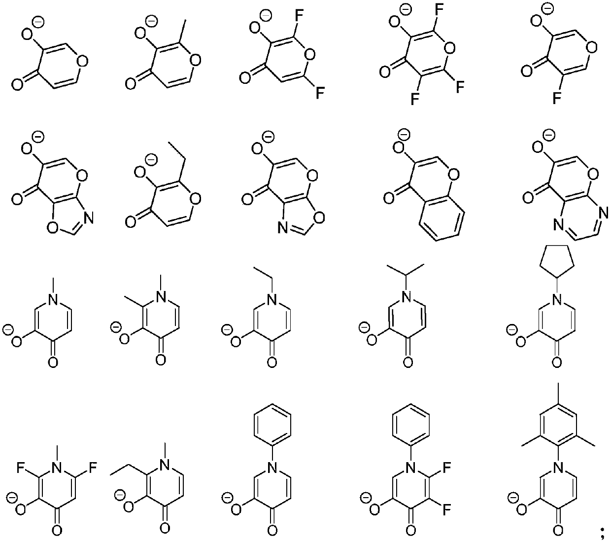
[0065] The iridium complex Ir28 was synthesized with reference to the method of Example 1, except that in step (2), the ligand A2 was used instead of the ligand A1 to obtain the iridium complex Ir28.

Embodiment 3

[0067] Synthesize iridium complex Ir31 with reference to the method for Example 1, difference is that adopt ligand II-B to replace ligand II-A in step (1), adopt ligand A2 to replace ligand A1 in step (2), through the same The reaction gives the iridium complex Ir31.


PUM

PropertyMeasurementUnit
Thicknessaaaaaaaaaa
Thicknessaaaaaaaaaa

Abstract

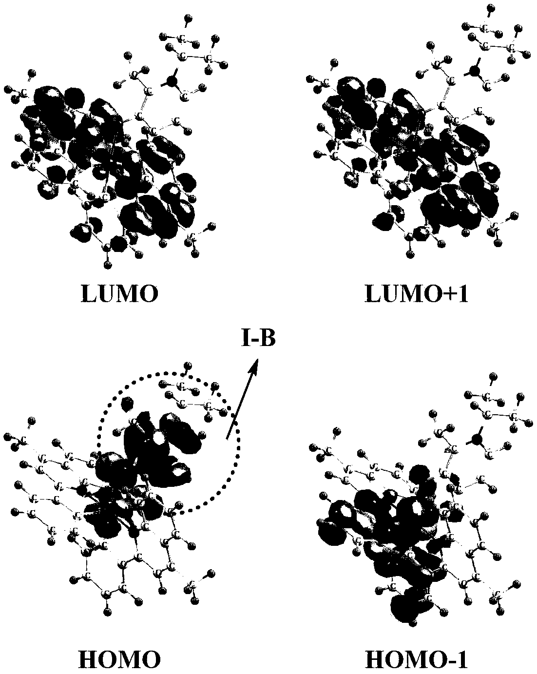
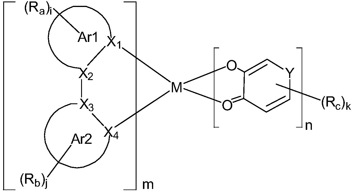
The invention belongs to the technical field of organic photoelectric materials, and particularly relates to a transition metal complex used as a phosphorescent material and application of the transition metal complex. Based on the brand-new material design concept, in the system, the names of a main ligand and an auxiliary ligand are not used any more because the selection and matching of the twoligands have very important influence on the properties of the material. According to the invention, two functional ligands are adopted, and front tracks of the two ligands both participate in an electronic structure in a luminous state, so that the two ligands can adjust and improve the luminous color and efficiency of the phosphorescent material; meanwhile, the molecular weight of the materialis not very large, and further material sublimation and purification and device preparation are facilitated.

Description

technical field [0001] The invention belongs to the technical field of organic photoelectric materials, in particular to a class of transition metal complexes used as phosphorescent materials and applications thereof. Background technique [0002] Liquid crystal display technology is one of the most mature flat panel display technologies at present. It has extensive and mature applications in notebook computers, mobile phones, etc., but it has slow response speed, difficulty in preparing large-area devices, high requirements for working conditions, and poor resistance. Disadvantages such as higher power consumption determine that it cannot meet higher requirements. From the perspective of development, organic electroluminescence (OLED), as one of the next-generation flat panel display technologies, has strong competitiveness and huge market potential. It has active light emission, wide viewing angle, low driving voltage, low power consumption, responsive At the same time, d...

Claims


Application Information

Patent Timeline
IPC IPC(8): C07F15/00C09K11/06H01L51/50H01L51/54
CPCC07F15/0033C07F15/0086C07F15/006C09K11/06C09K2211/185H10K85/341H10K85/346H10K85/342H10K50/11
Inventor 陈跃丰佩川孙伟胡灵峰杨阳王林
Owner YANTAI XIANHUA OPTOELECTRONICS INST CORP LTD
Learn More