Coke oven raw gas and waste gas waste heat recycling system

A waste heat recovery and waste gas technology, applied in the heating of coke ovens, coke ovens, waste heat treatment, etc., can solve the problems of high cost, waste heat sensible heat, and inability to recover heat energy of coke oven waste gas, etc., and achieve good economic benefits

Pending Publication Date: 2020-06-26
平罗县阳光焦化有限公司
View PDF0 Cites 1 Cited by
  • Summary
  • Abstract
  • Description
  • Claims
  • Application Information

AI Technical Summary

Problems solved by technology

[0002] A coke oven contains dozens of carbonization chambers (such as 56). These carbonization chambers produce a large amount of raw coal gas at 600-800°C during operation, which has high heat energy. The raw coal gas generated during the carbonization process in the carbonization chamber is collected into the top space of the carbonization chamber, and enters the gas collecting pipe through the riser pipe and the bridge pipe. The raw coal gas is directly sprayed with ammonia water in the bridge pipe and cooled to about 85°C. The cooled raw coal gas contains a large amount of tar and other components, the temperature is still high, and it needs to undergo various treatments to become coke oven gas, resulting in high cost of coke oven gas to natural gas (SNG, CNG, LNG), and natural gas products lack obvious competitiveness
This process not only wastes a large amount of thermal energy sensible heat in raw gas, but also wastes light tar, heavy tar and other components in raw gas with high economic value.
[0003] While the c

Method used


Image

  • Coke oven raw gas and waste gas waste heat recycling system
  • Coke oven raw gas and waste gas waste heat recycling system
  • Coke oven raw gas and waste gas waste heat recycling system

Examples


Embodiment Construction

[0022] In order to more clearly illustrate the technical solutions of the embodiments of the present invention, the following will briefly introduce the accompanying drawings that need to be used in the embodiments. Obviously, the accompanying drawings in the following description are some embodiments of the present invention. Ordinary technicians can also obtain other drawings based on these drawings without paying creative work.

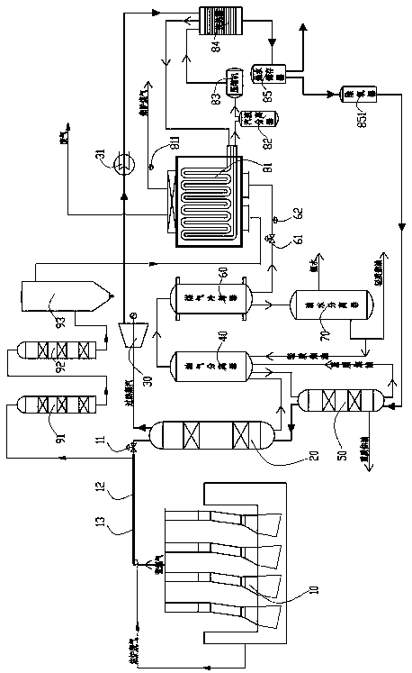
[0023] see Figure 1 to Figure 3, The present invention provides a coke oven raw gas and exhaust gas waste heat recovery and reuse system, including a coke oven 10, a high-temperature waste heat boiler 20, a steam turbine 30, an oil-gas separator 40, a low-temperature waste heat boiler 50, a gas cooler 60, and an oil-water separator 70. Low-temperature waste heat recovery device, the raw gas outlet end of the coke oven 10 is connected to the first inlet of the high-temperature waste heat boiler 20, so as to transport a large amount of raw gas at 60...


PUM


Abstract

The invention discloses a coke oven raw gas and waste gas waste heat recycling system. The coke oven raw gas and waste gas waste heat recycling system comprises a coke oven, a high-temperature waste heat boiler, a waste gas purifying device, a steam turbine, an oil-gas separator, a low-temperature waste heat boiler, a coal gas cooler, an oil-water separator and a low-temperature waste heat recycling device. According to the scheme adopted by the invention, the high-temperature waste heat boiler, the low-temperature waste heat boiler and the low-temperature waste heat recycling device are simultaneously arranged, so that raw gas high-temperature sensible heat, heavy tar low-temperature waste heat and 60-100-DEG C raw gas low-temperature waste heat are effectively recycled and reutilized, and a great deal of heavy tar and light tar in raw gas further can be recycled, and therefore, profits are created and the yield is increased for enterprises, and economic and social benefits are very good; raw gas is further conveyed into a first smoke gas pipeline to perform heat exchange with coke oven waste gas in a second smoke gas pipeline, so that high-temperature sensible heat in the raw gasis partially recycled and reutilized; and in a coke oven waste gas denitration process, a heater does not need to additionally arrange, so that coke oven waste gas investment and treatment cost is greatly reduced, and energy conservation and consumption reduction of coking enterprises are facilitated.

Description

technical field [0001] The invention relates to the technical field of coke oven waste heat recovery, in particular to a coke oven raw gas and waste gas waste heat recovery and reuse system. Background technique [0002] A coke oven contains dozens of carbonization chambers (such as 56). These carbonization chambers produce a large amount of raw coal gas at 600-800°C during operation, which has high heat energy. The raw coal gas generated during the carbonization process in the carbonization chamber is collected into the top space of the carbonization chamber, and enters the gas collecting pipe through the riser pipe and the bridge pipe. The raw coal gas is directly sprayed with ammonia water in the bridge pipe and cooled to about 85°C. The cooled raw coal gas contains a large amount of tar And other components, the temperature is still high, and it needs to go through a variety of treatments to become coke oven gas, which makes the cost of coke oven gas to natural gas (SNG,...

Claims


Application Information

Patent Timeline
IPC IPC(8): F22B1/18F22B33/18F22G1/16F22D1/50F27D17/00C10K1/00C10K1/04C10K1/06B01D46/02B01D53/48B01D53/56B01D53/75C10B29/00F01K11/02F01K17/02
CPCB01D46/02B01D53/48B01D53/56B01D53/75C10B29/00C10K1/001C10K1/002C10K1/04C10K1/06F01K11/02F01K17/02F22B1/18F22B33/18F22D1/50F22G1/16F27D17/004F27D17/008F27D2017/006Y02P10/25Y02P20/10Y02P20/129Y02P20/50
Inventor 司志刚牛永祥赵文萍石卫江万学明柴新华代欢徐小明邵学福
Owner 平罗县阳光焦化有限公司
Why Eureka
Try Eureka