Power generation system based on pressure constancy

A power generation system and pressure technology, applied in the direction of hydropower, engine components, machines/engines, etc., can solve the problems of large investment costs (several billions of RMB, dependence, serious cave resources, etc., to reduce the power consumption of water pumps , saving investment costs, the effect of simple system structure

Active Publication Date: 2020-07-10
STATE GRID HUNAN ELECTRIC POWER +2
View PDF15 Cites 7 Cited by
  • Summary
  • Abstract
  • Description
  • Claims
  • Application Information

AI Technical Summary

Problems solved by technology

However, the traditional compressed air energy storage power stations represented by the Huntorf compressed air energy storage power station in Germany and the McIntosh compressed air energy storage power station in the United States rely on external natural gas fuel supplementation, have an impact on the environment, and have low conversion efficiency of high-pressure air to electricity (less than 50%). Relying on large-volume cave resources and inflexible layout
At present, the most advanced advanced adiabatic compressed air storage often requires at least tens of thousands of cubic meters of large-volume abandoned mines and caves to store high-pressure air, which is seriously dependent on cave resources, inflexible layout, and high investment costs (every few billion RMB) ), the process of energy storage and energy release is in an adiabatic process, and there are problems of easy escape of heat and low conversion efficiency

Method used


Image

  • Power generation system based on pressure constancy
  • Power generation system based on pressure constancy
  • Power generation system based on pressure constancy

Examples


Embodiment Construction

[0053] The present invention will be further described below in conjunction with accompanying drawings and examples.

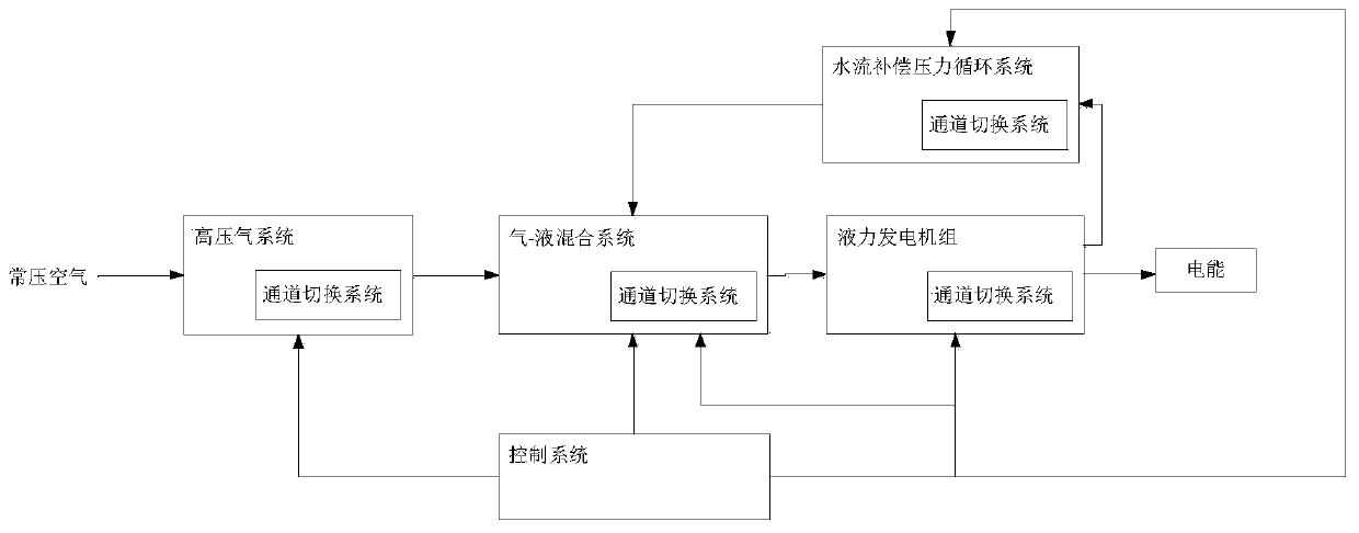
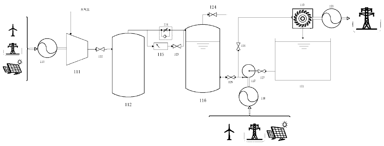
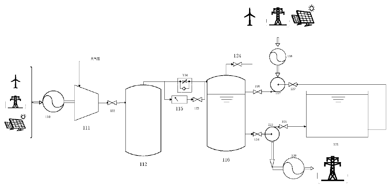
[0054] Such as figure 1 As shown, the present invention provides a power generation system based on constant pressure, including a high-pressure gas system, a gas-liquid mixing system, a hydraulic power generation unit, a channel switching system, a control system and a water flow compensation pressure circulation system, a high-pressure gas system, a gas-liquid The mixing system, hydraulic generator set, and water flow compensation pressure circulation system are connected through the channel switching system and controlled by the control system;

[0055] The high pressure gas system includes N 1 Group parallel high-pressure gas subsystem, N 1 ≥1;

[0056] Each group of high-pressure gas subsystems includes an air compression device and a high-pressure gas storage container connected in sequence, and the air compression device is used to provide the initia...


PUM


Abstract

The invention discloses a power generation system based on pressure constancy. The power generation system based on the pressure constancy comprises a high-pressure gas system, a gas-liquid mixing system, a hydraulic generator set, a channel switching system, a control system and a water flow compensation pressure circulation system, wherein the high-pressure gas system, the gas-liquid mixing system, the hydraulic generator set and the water flow compensation pressure circulation system are connected through the channel switching system, and are controlled through the control system. A water pump pumps water and compresses air in a variable-pipeline-characteristic down-conversion operation mode so that the water pump can operate near an efficient area all the time, the high efficiency is maintained, and electric energy consumed by water pumping of the water pump is reduced; a water turbine is stabilized near a rated water head in the power generation process so that the water turbine can operate near the highest efficiency area, and more electric energy is generated; and therefore, by consuming less electric energy, more electric energy is increased, so that the overall efficiencyfor converting power into power of the system is higher. The system has the functions of conventional compressed air energy storage and pumped storage power station large-scale electric energy storage, and has the characteristics of no dependence on terrain fall, high efficiency, long operation time and the like.

Description

technical field [0001] The invention relates to the technical field of new energy storage and power generation, in particular to a power generation system based on constant pressure. Background technique [0002] With the development of large-scale wind energy / photovoltaic resources, my country's wind power / photovoltaic development has maintained a strong momentum of rapid development. By the end of 2018, my country's renewable energy power installed capacity reached 728 million kilowatts, accounting for about 38.3% of the total power installed capacity , but the contradiction between the rapid development of new energy power generation and the relatively lagging power grid construction has become increasingly obvious. Large-scale wind power / photovoltaic energy connected to the grid with the characteristics of randomness, intermittency, anti-regulation and large output fluctuations has a great impact on the voltage stability, transient stability and frequency stability of the...

Claims


Application Information

Patent Timeline
Patent Type & Authority Applications(China)
IPC IPC(8): F04B35/04F04B41/02F04B17/03F04B23/02F04B49/06F04B49/22F03B13/00F03B15/00
CPCF04B35/04F04B41/02F04B17/03F04B23/02F04B49/065F04B49/225F03B13/00F03B15/00Y02E10/20Y02E60/16
Inventor 寇攀高朱光明张军肖剑陈德新翟建平
Owner STATE GRID HUNAN ELECTRIC POWER
Why Eureka
Try Eureka