Deposition method for cobalt-based gradient high-temperature wear-resistant anti-friction coating through laser-plasma composite energy field

A high-temperature wear-resistant and anti-friction coating technology, applied in the direction of coating, metal material coating process, etc., can solve the problems of reduced coating compactness and wear resistance, low bonding strength, and failure to reach theoretical life, etc. Achieve the effect of improving density and bonding force, improving high temperature performance and extending service life

Active Publication Date: 2020-07-24
BEIJING UNIV OF TECH
View PDF8 Cites 0 Cited by
  • Summary
  • Abstract
  • Description
  • Claims
  • Application Information

AI Technical Summary

Problems solved by technology

However, because the coating prepared by thermal spraying technology often presents a typical layered structure, the coating and the metal substrate are mechanically bonded, and the bonding strength is low; there are many pores and micro-cracks in the coating, resulting in a dense coating. The corrosion resistance and wear resistance are reduced, and the theoretical life cannot be reached, and the performance of the coating still has a large room for improvement.

Method used


Image

  • Deposition method for cobalt-based gradient high-temperature wear-resistant anti-friction coating through laser-plasma composite energy field
  • Deposition method for cobalt-based gradient high-temperature wear-resistant anti-friction coating through laser-plasma composite energy field
  • Deposition method for cobalt-based gradient high-temperature wear-resistant anti-friction coating through laser-plasma composite energy field

Examples


Embodiment 1

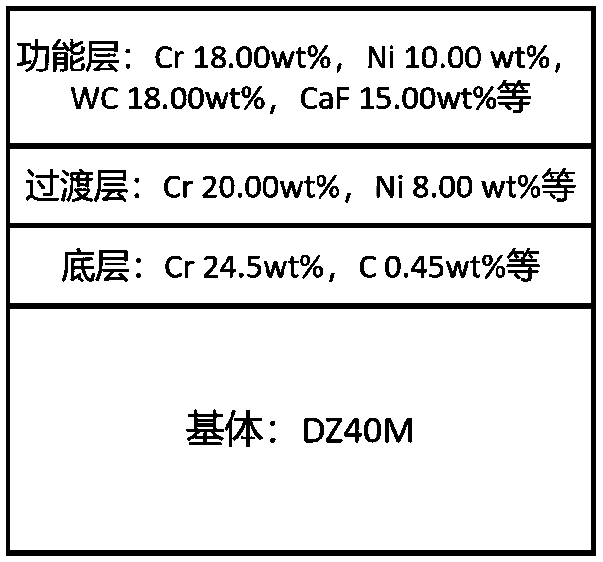
[0022] (1) Base material DZ40M, specification: 100mm*20mm*2mm, sandblasting to remove surface oil and increase roughness, after passing the inspection, install it on the fixture. The bottom layer powder: Cr 22.50wt%, C 0.45wt%, Ni 10.50wt%, W7.00wt%, Mo 0.20wt%, Fe 1.50wt%, Si 0.50wt%, Co balance; intermediate transition layer powder: Cr18. 00wt%, Ni 8.00wt%, Fe 1.20wt%, C 0.08wt%, WC7.00wt%, Co balance; surface functional layer powder composition: Cr 16.00wt%, Ni 10.00wt%, Fe 1.00wt%, WC 18.00 wt%, CaF 15.00wt%, and the balance of Co are put into corresponding powder feeding bins respectively.

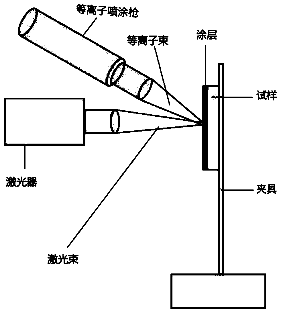
[0023] (2) Device preparation: adjust the position of the device so that the laser beam is 90°-100° to the surface of the part, the plasma spraying beam is 70°-90° to the surface of the part, the plasma beam and the powder beam are coaxial, and the plasma beam and the laser Beam recombination acts on common areas of the part surface. Set up the path execution program for the kinemat...

Embodiment 2

[0028] (1) Base material GH605, specification: 100mm*20mm*2mm, sandblasting to remove surface oil and increase roughness, after passing the inspection, install it on the fixture. The bottom layer powder: Cr 19.00wt%, C 0.10wt%, Ni 9.00wt%, W10.00wt%, Mo 0.40wt%, Fe 2.00wt%, Si 0.20wt%, Co balance. Intermediate transition layer powder: Cr 18.00wt%, Ni 8.00wt%, Fe 1.50wt%, C 0.08wt%, Si 0.10wt%, WC 8.00wt%, Co balance. Powder composition of surface functional layer: Cr 16.00wt%, Ni 8.00wt%, Fe 1.00wt%, WC 15.00wt%, CaF 12.00wt%, Co balance. Load them into the corresponding powder feeding bins respectively.

[0029] (2) Device preparation: adjust the position of the device so that the laser beam is 90°-100° to the surface of the part, the plasma spraying beam is 70°-90° to the surface of the part, the plasma beam and the powder beam are coaxial, and the plasma beam and the laser Beam recombination acts on common areas of the part surface. Set up the path execution program for ...

Embodiment 3

[0034] (1) Base material GH5188, specification: 100mm*20mm*2mm, sandblasting to remove surface oil and increase roughness, after passing the inspection, install it on the fixture. The bottom layer powder: Cr 20.00wt%, C 0.10wt%, Ni 14.00wt%, Fe2.00wt%, Si 0.20wt%, Co balance; intermediate transition layer powder: Cr 18.00wt%, Ni 12.00wt%, Fe1. 00wt%, C 0.08wt%, Si 0.10wt%, WC 8.00wt%, Co balance; surface functional layer powder composition: Cr14.00wt%, Ni 10.00wt%, Fe 1.00wt%, WC 12.00wt%, CaF 10.00 wt%, Co balance. Load them into the corresponding powder feeding bins respectively.

[0035] (2) Device preparation: adjust the position of the device so that the laser beam is 90°-100° to the surface of the part, the plasma spraying beam is 70°-90° to the surface of the part, the plasma beam and the powder beam are coaxial, and the plasma beam and the laser Beam recombination acts on common areas of the part surface. Set up the path execution program for the kinematic structure...


PUM


Abstract

The invention discloses a deposition method for preparing a cobalt-based gradient high-temperature wear-resistant anti-friction coating through a laser-plasma composite energy field, and belongs to the technical field of surface coatings. The method includes the steps of selecting materials, preparing alloy powder, and forming the coating on a high-temperature alloy base body by means of deposition through the laser-plasma composite energy field. The composite deposition coating is composed of three layers of gradient materials, including the bottom layer, the middle transition layer and the surface functional layer. The deposition coating formed through the laser-plasma composite energy field has the technological parameters of plasma spraying equipment power of 20-40 kw, the powder feeding rate of 10-20 g / min, the spraying distance of 250-350 mm, the powder carrier gas flow rate of 2.6-4.3 L / min, the laser power of 2500-4000 W, the round laser light spot diameter of 3-8 mm, the device scanning speed of 150-200 mm / s, the argon protective gas flow rate of 8-12 L / min and the overlap rate of 0.2-0.35. The density, wear-resistant performance and anti-corrosion performance of the coating prepared through the method are greatly improved compared with those of a coating prepared through a plasma spraying technology.

Description

technical field [0001] The invention relates to the field of high-temperature alloy wear-resistant and anti-friction coating materials, in particular to the field of high-temperature alloy materials for aerospace and laser composite plasma spraying coating methods. Background technique [0002] Cobalt-based superalloys are used in the aerospace field and have good high-temperature performance. They have high content of nickel and chromium elements, and have relatively good high-temperature strength and thermal fatigue resistance. At present, thermal spraying technology is mainly used to prepare wear-resistant and corrosion-resistant coatings on the surface of cobalt-based superalloy parts to make up for the lack of wear-resistant and corrosion-resistant properties. However, because the coating prepared by thermal spraying technology often presents a typical layered structure, the coating and the metal substrate are mechanically bonded, and the bonding strength is low; there ...

Claims


Application Information

Patent Timeline
IPC IPC(8): C23C24/10C22C19/07C22C32/00C22C30/00
CPCC23C24/103C22C19/07C22C32/0047C22C30/00
Inventor 杨胶溪王高生
Owner BEIJING UNIV OF TECH
Why Eureka
Try Eureka