
Self-regenerative continuous melt crystallization system and method

A melting crystallization, self-regenerating technology, applied in the direction of heat exchange cooling crystallization, solution crystallization, crystallization purification/separation, etc., can solve the problem that the growth rate of the crystal layer should not be too fast, the crystallization and sweating time is long, and the crystal bed suspension effect is poor, etc. problems, to achieve stable and continuous operation, improve heat and mass exchange efficiency, and increase the production capacity of equipment per unit volume.

Active Publication Date: 2020-08-18
天津乐科节能科技有限公司 +1
View PDF17 Cites 9 Cited by
  • Summary
  • Abstract
  • Description
  • Claims
  • Application Information

AI Technical Summary

Problems solved by technology

At present, due to the difficulty in the development of the structure of the continuous device, the melt crystallization is mostly operated in a batch mode, that is, the crystallization and sweating purification processes are alternately carried out in the same crystallization equipment, which requires constant switching of cold and hot media. The process steps are complicated and the process is long. Such as prior art CN104801059A, CN206008090U etc.
At the same time, the batch mode has many restrictions on the operation. For example, the growth rate of the crystal layer should not be too fast, otherwise the crystal layer will be loose and porous, which will reduce the strength of the crystal layer and trap more impurities; the sweating process is more sensitive to temperature control. Containing impurities, but also avoiding crystal layer breakage or falling off, so the time for crystallization and sweating is longer, and the production efficiency is low
However, the existing continuous melting and crystallization devices generally have problems such as low heat exchange efficiency, poor crystal bed suspension effect, and unstable operation, such as the prior art US005149445A

Method used


Image

  • Self-regenerative continuous melt crystallization system and method
  • Self-regenerative continuous melt crystallization system and method
  • Self-regenerative continuous melt crystallization system and method

Examples


Embodiment 1

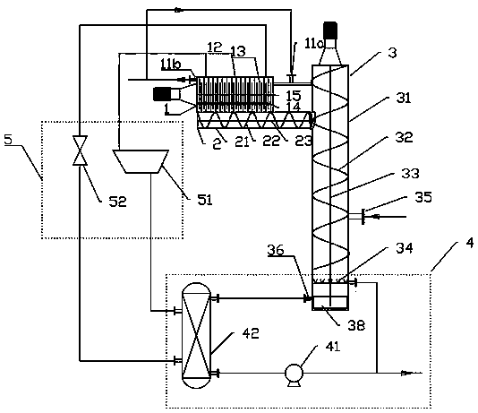
[0031]An external tube-plate heat exchanger is used to supply heat to the product recovery section, and the product with a high freezing point in the liquid phase is melted and recovered. Specifically, it is a self-reheating continuous melting crystallization system, which is characterized in that it includes crystallization section 1, crystal growth section 2, refining Section 3, product recovery section 4 and heat recovery system 5.

[0032] The crystallization section 1 includes a circulating feed inlet 11a, a discharge port 11b, a first cylinder body 12, a finned cooling fin 13 and a push scraper 14, wherein the finned cooling fin 13 is fixed on the first cylinder body 12, and the push scraper 14 is fixed On the first transmission shaft 15, the pushing scrapers 14 and the finned cooling fins 13 are alternately arranged at a certain angle, and the pushing scrapers 14 form an included angle of 15-75 degrees with the finned cooling fins along the material moving direction. Th...

Embodiment 2

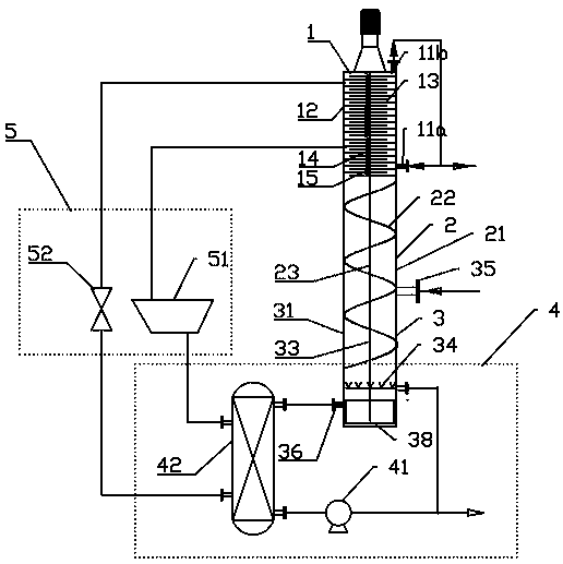
[0040] The inner-fin fin heat exchanger is used to supply heat to the product recovery section, and the liquid-phase high-freezing-point product is melted and recovered. Specifically, it is a self-reheating continuous melting crystallization system, which is characterized in that it includes a crystallization section 1 and a crystal growth section 2. , refining section 3, product recovery section 4 and heat recovery system 5.

[0041] The crystallization section 1 includes a circulating feed inlet 11a, a discharge port 11b, a first cylinder body 12, a finned cooling fin 13 and a push scraper 14, wherein the finned cooling fin 13 is fixed on the first cylinder body 12, and the push scraper 14 is fixed On the first transmission shaft 15, the pushing scrapers 14 and the finned cooling fins 13 are alternately arranged at a certain angle, and the pushing scrapers 14 form an included angle of 15-75 degrees with the finned cooling fins along the material moving direction. The finned ...

Embodiment 3

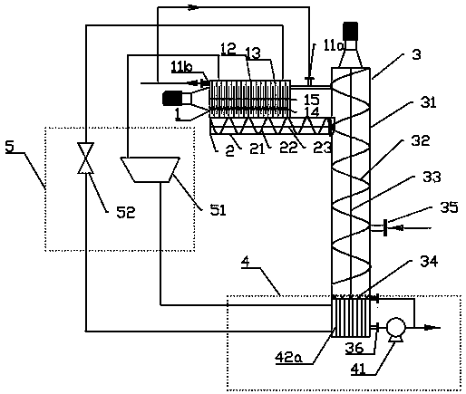
[0049] The product recovery section is heated by an inner-fin finned heat exchanger, and the product with a high freezing point in the liquid phase is melted and recovered. The specific implementation method is similar to that of Example 2. The component crystal particles melt when passing through the flow channel formed by the inner finned sheet 42a, part of the molten liquid is extracted as a product, and the remaining part of the molten liquid is reversed along the flow channel formed by the inner finned sheet 42a due to the extrusion of the solid particle settlement. Diffusion upwards to form a liquid phase countercurrent, and conduct heat and mass exchange with high melting point component crystal particles, so that the crystals complete the process of sweating and refining.


PUM


Abstract

The invention discloses a self-regenerative continuous melt crystallization system and method. The system comprises a crystallization section, a crystal growth section, a refining section, a product recovery section and a heat reuse system, wherein the crystallization section adopts a finned cooling fin structure to provide a cooling interface; a scraper is adopted to separate crystals generated on a cooling surface, so that the supercooled crystals enter a crystal growth section to grow, materials are conveyed to a refining section, crystal particles and high-melting-point product reflux flowreversely in the refining section to perform heat and mass transfer, and finally, high-purity and high-melting-point products are recovered through a product recovery section. The heat recycling system is connected with the finned cooling fins and the product recycling section heat exchanger, and heat recycling is achieved. The self-regenerative continuous melt crystallization system and method disclosed by the invention have the advantages of high production efficiency, high product purity, stable system operation, low energy consumption and the like, so that the defects of complex structure, low production efficiency and low energy utilization rate of the existing melt crystallization system are overcome.

Description

technical field [0001] The invention relates to the field of crystallization and separation, in particular to a self-reheating continuous melting crystallization system and method. Background technique [0002] With the continuous development of science and technology and the enhancement of environmental awareness, people put forward higher requirements for the purity of chemical products and the energy consumption control of chemical production process. Melting crystallization technology has attracted much attention because of its high purity of separated products, low process energy consumption, low operating temperature, low equipment corrosion, and is suitable for the separation of heat-sensitive and azeotropic systems. The basic principle is to separate by the difference in freezing point between the components of the mixture. Melt crystallization usually includes two processes of crystallization and sweating. The high freezing point components in the system are crysta...

Claims


Application Information

Patent Timeline
IPC IPC(8): B01D9/02C07C7/14C07C13/567C07C67/52C07C69/96
CPCB01D9/0013B01D9/005B01D9/0059B01D9/0063C07C7/14C07C67/52C07C2603/18C07C13/567C07C69/96Y02P20/10Y02P20/50
Inventor 夏君君于会满尹海蛟全晓宇陈玉林刘莉谢源圩
Owner 天津乐科节能科技有限公司
Learn More