
Optical power detection device of portable split-ring resonator loaded patch photoresistor

A split resonant ring and optical power detection technology, which is applied in measurement circuits and photometry using electric radiation detectors, can solve the problems of dark current limitation, small detection amplitude range, and low resolution, and improve detection sensitivity , reduce dark current, light weight effect

Active Publication Date: 2020-10-02
UNIV OF ELECTRONICS SCI & TECH OF CHINA
View PDF7 Cites 0 Cited by
  • Summary
  • Abstract
  • Description
  • Claims
  • Application Information

AI Technical Summary

Problems solved by technology

Commonly used amplifiers include linear amplifiers and logarithmic amplifiers; among them, the range of linear amplifiers is generally about 30dB, and in different operating ranges, they have different accuracy indicators. The closer to the lower limit of the range, the lower the accuracy value. Environmental impact; while the logarithmic amplifier has a larger range, generally its value can reach 60dB, and it has a relatively uniform temperature in the entire range, but due to the existing technology, the resolution in the range is too low, resulting in optical power The detection accuracy also decreases accordingly; moreover, the sampling range of the optical power of the traditional AD converter is generally within 0~20dBm, but the actual optical power is usually higher than 20dBm, at this time, the traditional AD converter will no longer fulfil requirements
At the same time, the traditional photoelectric detection technology relies on the change characteristics of the electrical properties of photosensitive materials under light irradiation. However, the lower limit of detection of electrical properties of photosensitive materials is limited by the dark current of materials.
[0004] To sum up, the detection amplitude range of the traditional optical power detection technology is small, and its use conditions and application range are limited by technology and cost. Power detection device

Method used


Image

  • Optical power detection device of portable split-ring resonator loaded patch photoresistor
  • Optical power detection device of portable split-ring resonator loaded patch photoresistor
  • Optical power detection device of portable split-ring resonator loaded patch photoresistor

Examples


Embodiment Construction

[0022] The present invention will be described in further detail below in conjunction with the accompanying drawings and embodiments.

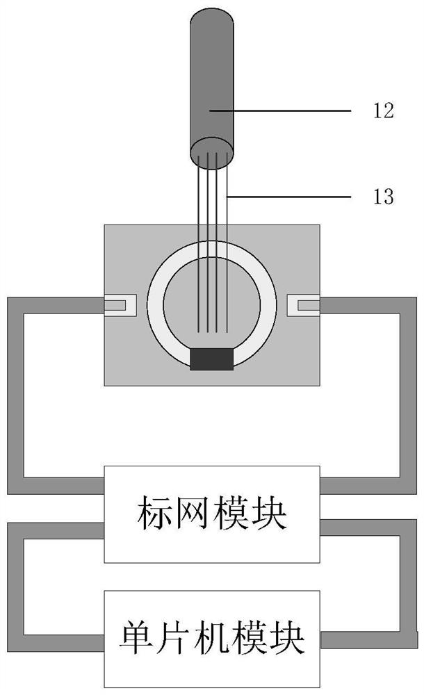
[0023] This embodiment provides a light (infrared) detection device with a portable split resonant ring loaded with a chip photoresistor, and its overall structure is as follows image 3 As shown, it specifically includes: a microwave resonant structure, a scalar network analyzer and a single-chip microcomputer module; the microwave resonant structure is connected to the scalar network analyzer through a coaxial line, and the scalar network analyzer is connected to the single-chip microcomputer module;

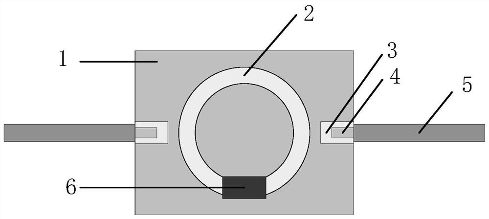
[0024] The microwave resonant structure adopts a split resonant ring circuit, such as figure 1 As shown, it specifically includes: a dielectric substrate 1, an split resonant ring 2 arranged on the upper surface of the dielectric substrate with the center of the circle at the center of the upper surface of the dielectric substrate, and a micro...


PUM


Abstract

The invention belongs to the field of optical power detection, and especially relates to an optical power detection device of portable split-ring resonator loaded patch photoresistor. The device comprises a microwave resonance structure, a scalar network analyzer and a single-chip microcomputer module, the microwave resonance structure adopts a split-ring resonator circuit, and the patch photoresistor is loaded at an opening of the split-ring resonator circuit; when illumination irradiated on the patch photoresistor is changed, the resonance peak value of the split-ring resonator circuit is changed, the resonance peak value is detected through the scalar network analyzer, then the resonance peak value offset detection is realized through the single-chip microcomputer module, and thus the optical power detection is realized. According to the optical power detection device, the photosensitive characteristic and the microwave resonance characteristic of a semiconductor material are perfectly combined, and the detection sensitivity of optical (infrared) weak signals is improved by several orders of magnitudes; and meanwhile, the device has the advantages of being small in structure, light in weight, low in cost, free of environmental interference, convenient to carry and the like.

Description

technical field [0001] The invention belongs to the field of optical power detection, and specifically provides an optical power detection device with a portable split resonant ring loaded with a patch photoresistor. Background technique [0002] With the rapid development of optical fiber network technology and optical communication technology, the requirements for optical power detection are getting higher and higher. Changes in optical power can easily lead to communication and network failures. In the field of optical communication, in order to ensure the continuity, stability and safety of the work between devices, all optical devices are usually tested. [0003] The current optical (infrared) power detection method is mainly based on AD conversion, and the voltage signal of the measured photosensitive device (APD (avalanche photo detector, avalanche photodiode or PIN tube) under the light irradiation signal is amplified and sampled through the amplifier. , to realize ...

Claims


Application Information

Patent Timeline
Patent Type & Authority Applications(China)
IPC IPC(8): G01J1/42G01J1/44
CPCG01J1/42G01J1/44
Inventor 王健宇李恩李亚峰宋鑫张金涛余承勇
Owner UNIV OF ELECTRONICS SCI & TECH OF CHINA
Learn More