
Niobium-iron alloy continuous production device and production method

A ferroniobium alloy and production device technology, which is applied in the field of continuous production devices for ferroniobium alloy, can solve the problems of increasing chemical composition segregation and inhomogeneity, increasing metal loss in the crushing process, and difficult clean production technology, so as to achieve convenient and efficient production, Significant social and economic benefits, technological progress and innovation demonstration effects

Active Publication Date: 2020-10-16
CHINA MOLYBDENUM
View PDF8 Cites 1 Cited by
  • Summary
  • Abstract
  • Description
  • Claims
  • Application Information

AI Technical Summary

Problems solved by technology

[0004] The outstanding features of the current process are intermittent production operations, which limit the improvement of production efficiency; the thermal efficiency of the process is low, and the production cost is high; due to the limitation of the intermittent single-furnace operation mode, the metal loss in the form of rich slag is relatively large, resulting in The overall recovery rate is low; the advantages of the high-temperature liquid molten alloy granulation process cannot be used, which increases the metal loss in the crushing process; the iron ingot is easily affected by the temperature gradient during the solidification and crystallization process, resulting in dendritic crystallization, which increases the segregation of chemical components and inhomogeneity, reducing the physical properties of ferroalloys; it is difficult to realize clean production technology; the controllability of smelting is poor, and it is difficult to optimize and adjust the process in the smelting process, etc.

Method used


Image

  • Niobium-iron alloy continuous production device and production method
  • Niobium-iron alloy continuous production device and production method

Examples


Embodiment Construction

[0034] The present invention can be explained in more detail through the following embodiments. The purpose of disclosing the present invention is to protect all changes and improvements within the scope of the present invention. The present invention is not limited to the following embodiments;

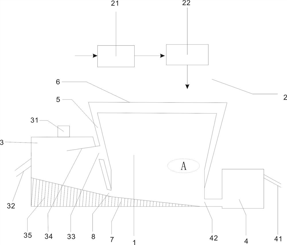
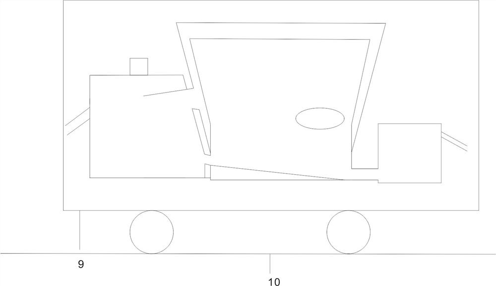
[0035] A continuous production device of ferroniobium alloy described in conjunction with the attached drawings, including

[0036] A smelting furnace 1;

[0037] A slag tank 3, the lower end of the side of the slag tank 3 communicates with the bottom of the side of the smelting furnace 1 through a siphon port 8, a slag discharge port 32 is provided on the side wall of the slag tank 3, and the smelting furnace 1, The slag tank 3 and the slag discharge port 32 together form a siphon structure; with the continuous input of materials in the smelting furnace 1, the continuous reaction, the generated waste slag continuously enters the slag tank 3, and the waste in the slag tank 3 will also pass ...


PUM


Abstract

The invention provides a niobium-iron alloy continuous production device and a production method. The device comprises a smelting furnace, a slag pool and an alloy molten pool; and an alloy generatedin the smelting furnace is molten through siphon separation to discharge from the alloy molten pool, and waste slag is discharged from the slag pool. The device can realize continuous production of aniobium-iron alloy, is higher in heat utilization efficiency in the process, improves the utilization rate of waste heat by above 20%, can further reduce the use level of a smelting furnace material heating agent, realizes clean production of the iron alloy, is low in comprehensive energy consumption, is prominent in energy saving and consumption reducing effects, greatly reduces the production cost, in particular, can realize the reduction operation of production procedures through application of a thermal molten alloy granulation breakage-free process, greatly reduces the slag-rich generation ratio compared with an intermittent production process, improves the procedure metal yield by 2% or above, is excellent in comprehensive economic benefit, improves the production efficiency by above30% compared with a traditional process, is convenient and efficient in production, is environment-friendly, is obvious in technical progress and innovation demonstration effect, improves the productquality, and is prominent in social and economic benefits.

Description

Technical field: [0001] The invention belongs to the technical field of ferro-niobium alloy production, and particularly relates to a continuous production device and a production method of ferro-niobium alloy. Background technique: [0002] Niobium is a rare metal with a high melting point. Metal niobium can be combined with iron in any ratio to produce a ferro-niobium alloy with a lower melting point. In particular, FeNb65 standard ferro-niobium alloy with a melting point lower than 1600 degrees and good fluidity in smelting conditions can be easily used as a niobium element additive by diffusion in the metallurgical melt, and is widely used in the special steel metallurgy industry. [0003] At present, in the field of ferroniobium production, the metal thermal reduction method is widely used to produce ferro-niobium alloy by batch and block methods. The process follows the calculation of ingredients, material mixing, upper or lower ignition smelting, sedative block, solidificati...

Claims


Application Information

Patent Timeline
Patent Type & Authority Applications(China)
IPC IPC(8): F27D3/14F27D3/15F27D7/06F27D13/00F27D17/00C22C1/02C22C27/02C22C35/00
CPCF27D3/1545F27D3/1509F27D3/14F27D7/06F27D17/004F27D13/002C22C1/02C22C27/02C22C35/00
Inventor 朱要武琚成新高湛伟候凯
Owner CHINA MOLYBDENUM
Learn More