Rapid sintering equipment for dynamically loading coupling alternating current and sintering method

A dynamic loading and rapid sintering technology, applied in the field of sintering, can solve the problems of unsatisfactory elimination of nano-powder hard agglomeration, achieve good industrial application prospects, reduce sintering temperature, and promote the effect of particle rearrangement

Inactive Publication Date: 2020-11-10
TSINGHUA UNIV
View PDF10 Cites 5 Cited by
  • Summary
  • Abstract
  • Description
  • Claims
  • Application Information

AI Technical Summary

Problems solved by technology

In addition, spark plasma sintering adopts static loading, which is not ideal for the elimination of hard agglomeration of nanopowders

Method used


Image

  • Rapid sintering equipment for dynamically loading coupling alternating current and sintering method
  • Rapid sintering equipment for dynamically loading coupling alternating current and sintering method
  • Rapid sintering equipment for dynamically loading coupling alternating current and sintering method

Examples


Embodiment 1

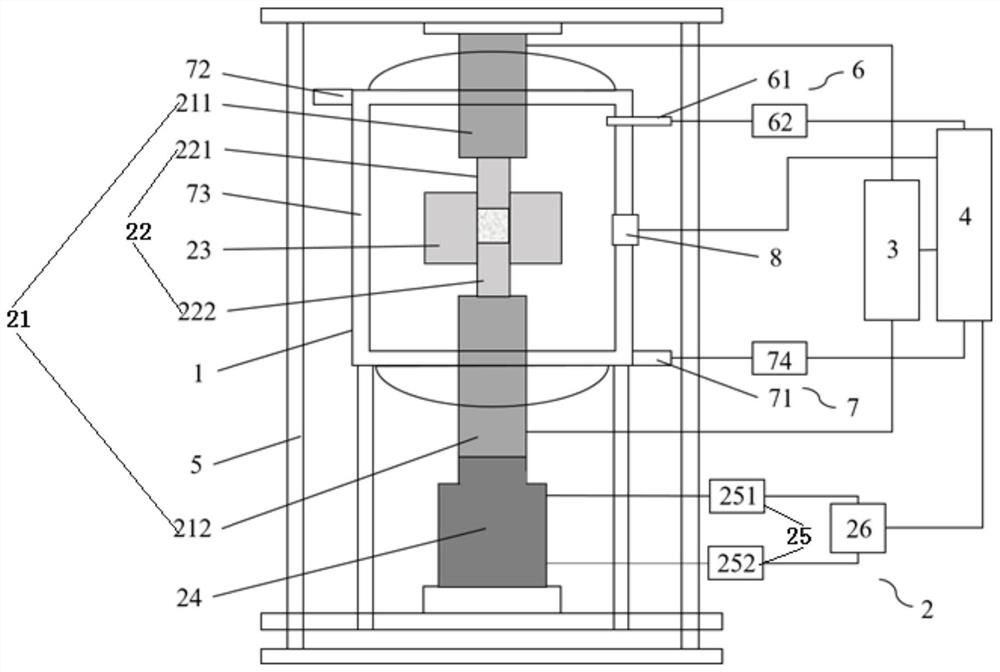
[0043] Such as Figure 1-3 As shown, this embodiment provides a dynamic loading coupled alternating current rapid sintering equipment, including the following components:

[0044] A furnace frame 5, a furnace body 1 is arranged in the furnace frame 5, and an airtight pressure-holding cabin is formed in the furnace body 1;

[0045] The dynamic loading system 2 includes a dynamic loading generation part and a dynamic loading control part, the dynamic loading generation part is set in the pressure holding cabin, and is used for pressurizing and heating the sintered material; the dynamic loading control part is set outside the pressure holding cabin, and the dynamic loading The output terminal of the load control part is connected with the dynamic load generation part, and is used for outputting the coupled total dynamic load to the dynamic load generation part;

[0046] The sintering control system 4 is arranged outside the pressure holding cabin, the output end of the sintering...

Embodiment 2

[0060] Such as Figure 1-3 As shown, this embodiment relates to a sintering method of a fast sintering device dynamically loaded with coupled alternating current, including the following steps:

[0061] a Check the rapid sintering equipment and put in the materials to be sintered;

[0062] b Input the sintering process parameters through the sintering control system 4;

[0063] c According to the requirements of the sintering process parameters, the sintering control system 4 vacuumizes the pressure holding chamber or injects gas (such as argon, nitrogen, etc.) through the atmosphere control system 6, and starts to operate after the air pressure in the pressure holding chamber reaches the set value Sintering procedure;

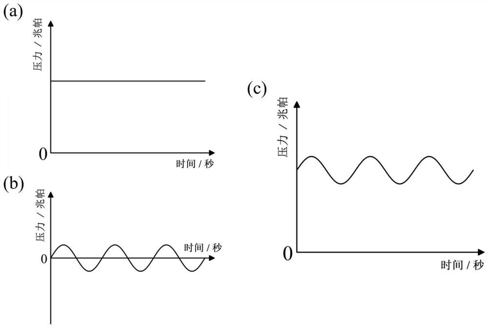
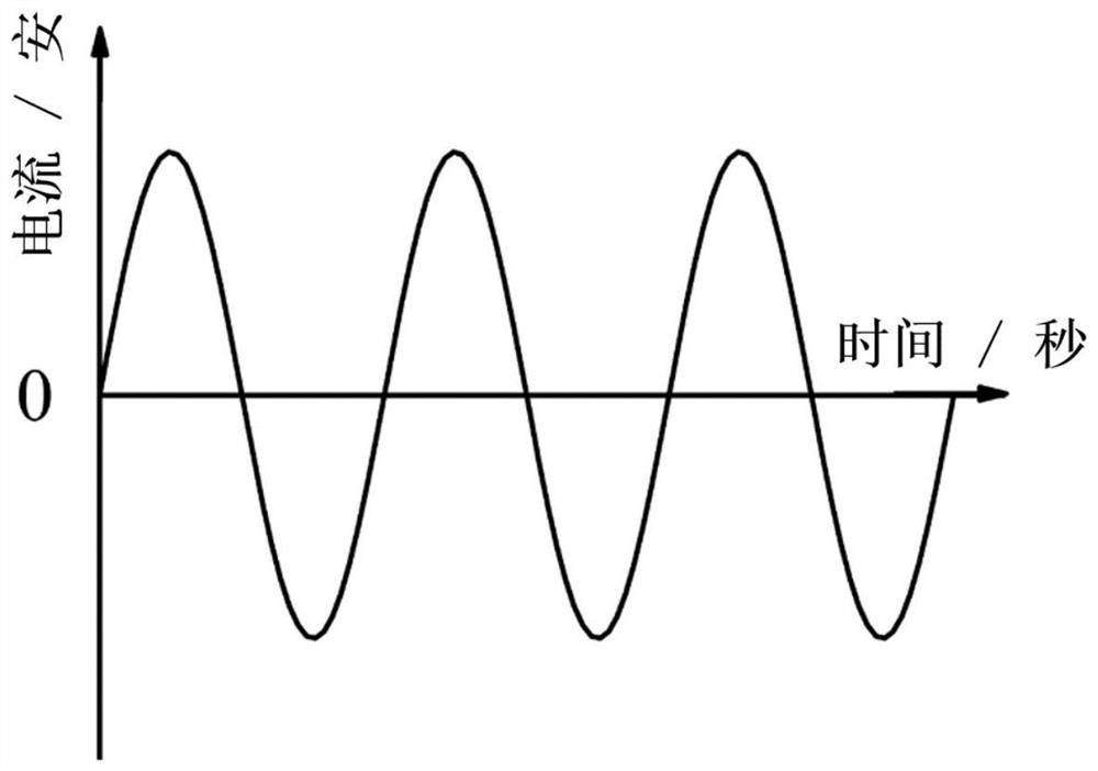
[0064] d According to the requirements of the sintering process parameters, the parameters of the total dynamic loading are adjusted and applied through the sintering control system 4 and the dynamic loading system 2;

[0065] e According to the requirement...


PUM


Abstract

The invention relates to rapid sintering equipment for dynamically loading coupling alternating current. The rapid sintering equipment comprises the following components including a furnace frame, a dynamic loading system,a sintering control system and an alternating current control system; a furnace body is arranged in the furnace frame, and a closed pressure maintaining cabin is formed in the furnace body; the dynamic loading system comprises a dynamic loading generation part and a dynamic loading control part, and the dynamic loading generation part is arranged in the pressure maintaining cabin and used for heating a sintering material; the dynamic loading control part is arranged outside the pressure maintaining cabin, the output end of the dynamic loading control part is connected with the dynamic loading generation part, and the dynamic loading control part is used for outputting coupled total dynamic loading to the dynamic loading generation part; the sintering control system isarranged outside the pressure maintaining cabin, and the output end of the sintering control system is connected with the input end of the dynamic loading control part; and the alternating current control system is arranged outside the pressure maintaining cabin, the input end of the alternating current control system is connected with the output end of the sintering control system, and the output end of the alternating current control system is connected with the dynamic loading generation part. The equipment can remarkably improve the sintering driving force, inhibit grain growth, improve the density of a sintered body and improve the material performance.

Description

technical field [0001] The invention relates to a fast sintering device and a sintering method for dynamically loading coupled alternating current, and belongs to the technical field of sintering. Background technique [0002] Sintering is one of the most critical steps in the preparation of advanced structural and functional materials such as high-performance ceramics. In the traditional pressureless sintering process, the surface curvature of the powder is the only sintering driving force. When the temperature rises, the material to be sintered undergoes diffusion and mass transfer under the action of the sintering driving force, the porosity of the system decreases, the density increases, and finally a dense bulk material is obtained. However, in the later stage of sintering, the surface curvature of the grains decreases, the driving force for further densification decreases significantly, the residual pores cannot be effectively discharged, and even the grains grow abno...

Claims


Application Information

Patent Timeline
Patent Type & Authority Applications(China)
IPC IPC(8): F27B17/00F27D7/06F27D9/00F27D11/10F27D19/00F27D21/00
CPCF27B17/00F27D7/06F27D9/00F27D11/10F27D19/00F27D21/0014F27D2007/063F27D2019/0009F27D2019/0037
Inventor 谢志鹏许靖堃
Owner TSINGHUA UNIV
Why Eureka
Try Eureka