Solid-liquid separation equipment and use method thereof and sewage treatment system

A solid-liquid separation and equipment technology, applied in water/sewage treatment, water/sewage treatment equipment, water/sludge/sewage treatment, etc. To achieve the effect of improving sewage treatment effect, improving sewage treatment effect and improving effect

Inactive Publication Date: 2020-11-27
李玲
View PDF7 Cites 0 Cited by
  • Summary
  • Abstract
  • Description
  • Claims
  • Application Information

AI Technical Summary

Problems solved by technology

Most of the above-mentioned traditional coal-water treatment needs to be equipped with coal-water sedimentation tanks. In order to ensure the treatment effect, the coal-water sedimentation tanks are generally configured in two stages, which greatly increases the occupied area and reduces the space utilization rate; in addition, the pre-sedimentation tank is easy to Interference from unstable incoming water from the outside will also affect the stability of the effluent quality of the entire system
[0003] Although some solid-liquid separation equipment has also appeared in the prior art, which can save the coal-water sedimentation tank, reduce the occupied area to a certain extent, and improve the space utilization rate, but it is still easily disturbed by unstable incoming water. , and the effect of its flocculation reaction is poor, its sewage treatment effect is not ideal, and the water quality of the discharged clear water is poor

Method used


Image

  • Solid-liquid separation equipment and use method thereof and sewage treatment system
  • Solid-liquid separation equipment and use method thereof and sewage treatment system
  • Solid-liquid separation equipment and use method thereof and sewage treatment system

Examples


Embodiment Construction

[0028] The present invention is described below based on examples, but the present invention is not limited to these examples. In the following detailed description of the present invention, some specific details are described in detail, and in order to avoid obscuring the essence of the present invention, known methods, procedures, procedures, and components are not described in detail.

[0029] Additionally, those of ordinary skill in the art will appreciate that the drawings provided herein are for illustrative purposes and are not necessarily drawn to scale.

[0030] Unless the context clearly requires, throughout the specification and claims, "comprises", "comprises" and similar words should be interpreted in an inclusive sense rather than an exclusive or exhaustive meaning; that is, "including but not limited to" meaning.

[0031] In the description of the present invention, it should be understood that the terms "first", "second" and so on are only used for descriptive...


PUM


Abstract

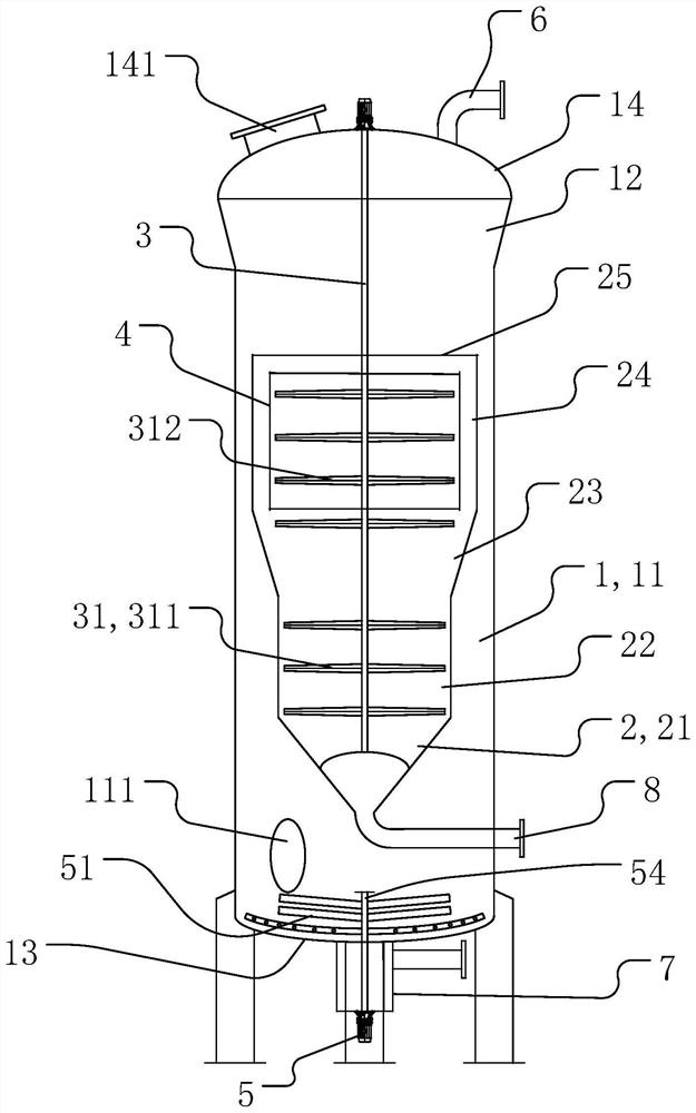
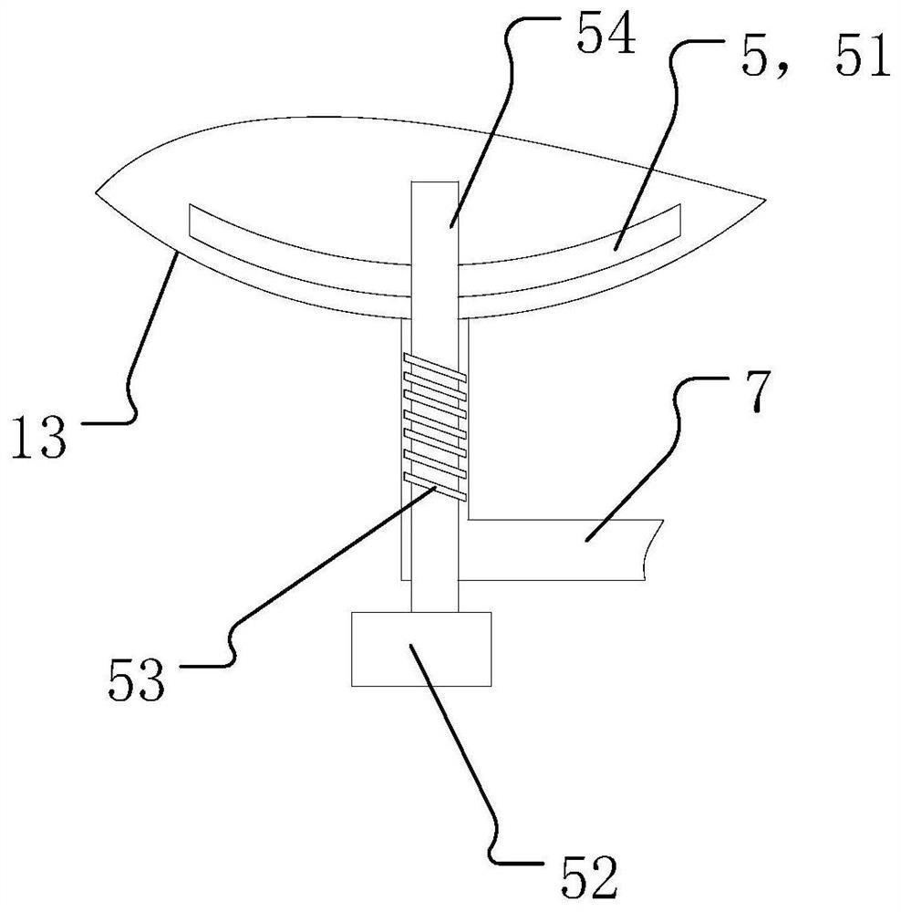
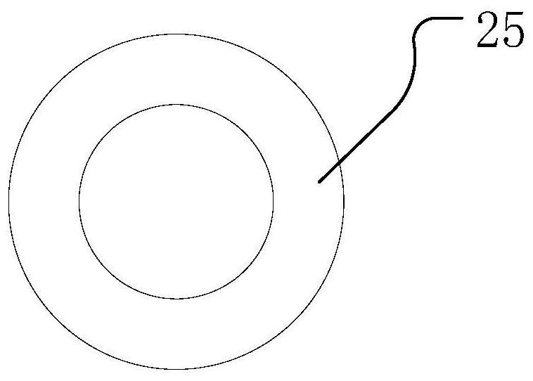
The invention provides solid-liquid separation equipment and a use method thereof and a sewage treatment system. The solid-liquid separation equipment comprises an inner cylinder suspended on the inner side of an outer cylinder, the stirring part is positioned on the radial inner side of the inner cylinder, and the inner cylinder is fixedly connected with the outer cylinder; the inner cylinder comprises a flocculation straight cylinder at the top; the top end of the flocculation straight cylinder is open; an annular separation plate is arranged at the top end of the flocculation straight cylinder; and the outer edge of the separation plate is connected with the flocculation straight cylinder. The solid-liquid separation equipment also comprises a movable weir straight cylinder; and the movable weir straight cylinder is located on the inner side of the flocculation straight cylinder, the top end of the movable weir straight cylinder is lower than the separation plate, and the inner ringdiameter of the separation plate is smaller than the diameter of the movable weir straight cylinder. The solid-liquid separation equipment is reasonable in structural layout; and through the structural layout of the outer cylinder, the inner cylinder, the flocculation straight cylinder in the inner cylinder, the separation plate and the movable weir straight cylinder, the flocculation reaction effect of sewage raw materials and sewage treatment agents in the inner cylinder can be better improved, and then the sewage treatment effect is improved.

Description

technical field [0001] The invention relates to the technical field of water treatment, in particular to a solid-liquid separation device and a sewage treatment system. Background technique [0002] At present, in the production and operation of electric power, electronics, metallurgy, petrochemical, mining and other industries, a large amount of ash-containing mineral washing wastewater and production wastewater (such as: sludge discharge water, coal-containing wastewater, graphite wastewater, silicon crystal wastewater, etc.) , This kind of wastewater has high turbidity and high content of suspended solids. For example, coal water treatment in thermal power plants and coal mines mainly uses the following devices: electrocoagulation devices, high-efficiency coagulation purifiers, and high-efficiency coagulation clarification devices. Most of the above-mentioned traditional coal-water treatment needs to be equipped with coal-water sedimentation tanks. In order to ensure the...

Claims


Application Information

Patent Timeline
IPC IPC(8): C02F1/52C02F11/121
CPCC02F1/5281C02F11/121C02F2201/002C02F2201/004C02F2303/14
Inventor 李玲
Owner 李玲
Why Eureka
Try Eureka