Circulating spouting type NOx emission reduction system and working method thereof

A spouting and reactor technology, applied in the field of circulating spouting NOx emission reduction system, can solve the problems of reducing the output and quality of clinker, low overall efficiency, and high cost of use, and achieve the effect of eliminating influence and improving emission reduction efficiency.

Pending Publication Date: 2020-12-11
NANJING KISEN INT ENG
View PDF0 Cites 2 Cited by
  • Summary
  • Abstract
  • Description
  • Claims
  • Application Information

AI Technical Summary

Problems solved by technology

[0004] Selective non-catalytic reduction (SNCR) technology is to spray the ammonia solution into the appropriate position of the decomposition furnace and preheater through the pump station and the spray gun, and reduce the NO X reduced to N 2 and H 2 O, thus achieving NO X Emission reduction; the main problem of this technology is that the denitrification efficiency is greatly affected by temperature and the overall efficiency is low. During the production of cement enterprises, there will be temperature fluctuations in the kiln, and the temperature at the place where ammonia water is injected will deviate from its optimal reaction temperature. In order to ensure the outlet discharge The index can only increase the amount of ammonia water, which will greatly increase the cost of cement production and at the same time produce a large amount of ammonia escape, causing secondary pollution; at the same time, the overall efficiency of this technology is generally around 60%, and ultra-low emissions cannot be achieved
[0005] Selective catalytic reduction (SCR) technology is to introduce flue gas into the reactor (equipped with catalyst), and spray ammonia solution into the appropriate position of the connecting pipe, under the action of certain temperature and catalyst, NO X reduced to N 2 and H 2 O, thus achieving NO X Emission reduction; the main problems of this technology are high investment cost, high post-use cost, denitrification efficiency is greatly affected by temperature and dust concentration, and the flue gas outlet temperature of cement enterprises is low. The common solution is to arrange the reactor between the calciner and the Between waste heat boilers, the temperature here meets the requirements for catalyst use, but the dust concentration is high, which can easily cause catalyst pore blockage, and the denitrification efficiency is greatly reduced in the later period of use. The catalyst needs to be replaced regularly, and the use cost is high. At the same time, the aging catalyst is hazardous waste. It is extremely difficult to handle, causing secondary pollution
[0006] The common scheme of staged combustion technology is to add a section of pipe (reactor) between the smoke chamber of the rotary kiln and the calciner, and connect the tertiary air of the kiln head into the pipe from the side, and at the same time, insert raw material and fuel at its appropriate position, Using the "Budual" reaction, the CO 2 Reduce to CO, or use fuel pyrolysis gasification to generate CO, C X h y Reducing gas, and then the NO generated at high temperature in the rotary kiln X reduced to N 2 and CO 2 , thus achieving NO X Emission reduction; the main problem of this technology is that the accumulation of material at the bottom of the calciner is serious. After the accumulation of material enters the rotary kiln, it will increase the load of the rotary kiln, reduce the output and quality of clinker, and have a great impact on normal production.

Method used


Image

  • Circulating spouting type NOx emission reduction system and working method thereof
  • Circulating spouting type NOx emission reduction system and working method thereof

Examples


Embodiment Construction

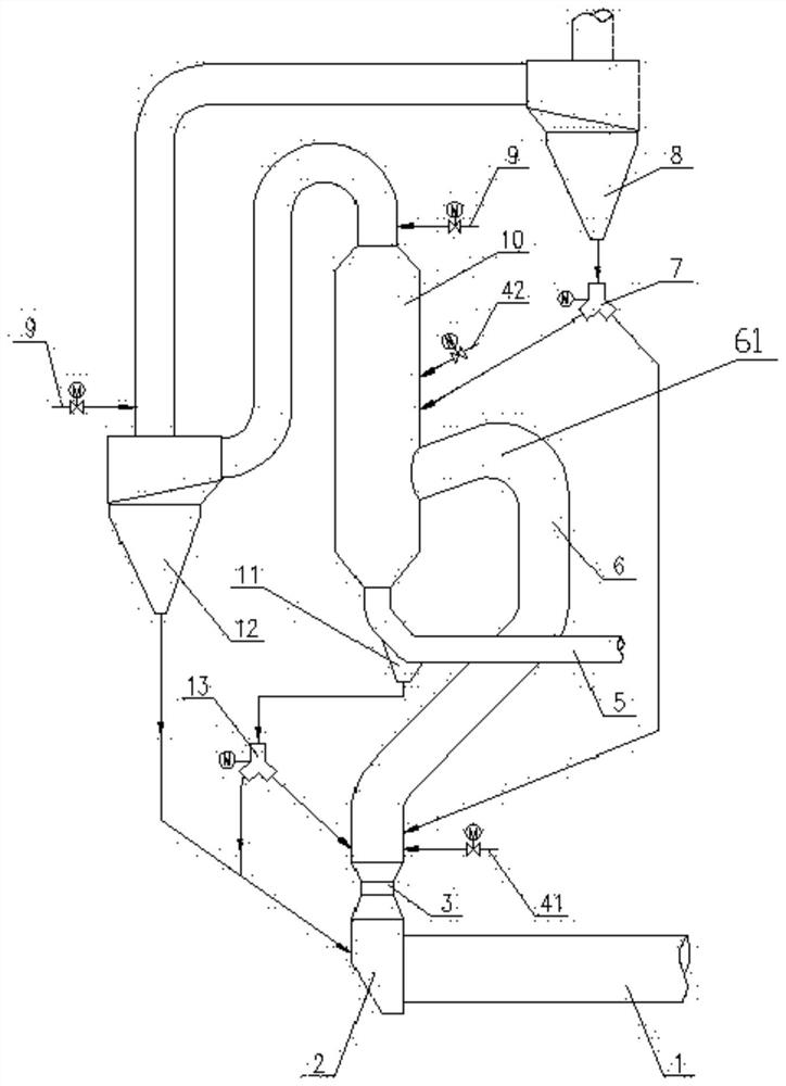
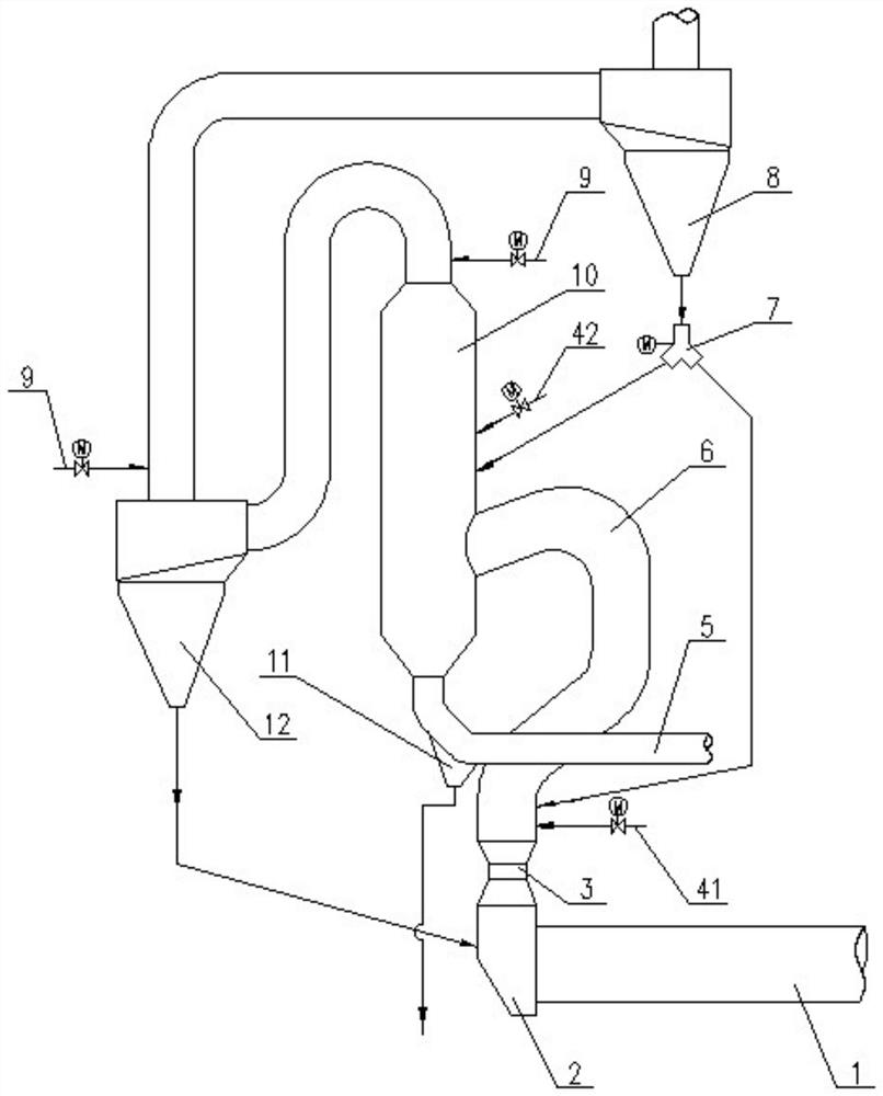
[0021] Unless otherwise defined, the technical terms or scientific terms used in the present invention shall have the usual meanings understood by those skilled in the art to which the present invention belongs. "First", "second" and similar words used in the present invention do not indicate any order, quantity or importance, but are only used to distinguish different components. "Comprising" or "comprising" and similar words mean that the elements or items appearing before the word include the elements or items listed after the word and their equivalents, without excluding other elements or items. Words such as "connected" or "connected" are not limited to physical or mechanical connections, but may include electrical connections, whether direct or indirect. "Up", "Down", "Left", "Right" and so on are only used to indicate the relative positional relationship. When the absolute position of the described object changes, the relative positional relationship may also change acc...


PUM


Abstract

The invention relates to a circulating spouting type NOx emission reduction system and a working method thereof. The circulating spouting type NOx emission reduction system comprises a rotary kiln, asmoke chamber, a spouting ring, a fuel system, a tertiary air pipe, a reactor, a first material distribution valve, a first cyclone cylinder, a denitration system, a decomposing furnace, a hopper anda second cyclone cylinder. An air inlet of the smoke chamber is connected with an air outlet of the rotary kiln, an air outlet of the reactor is connected to one side of the decomposing furnace and communicated with the interior of the decomposing furnace, and an air inlet of the reactor is connected with an air outlet of the smoke chamber through the spouting ring. An air outlet of the tertiary air pipe is connected to the bottom of the decomposing furnace, a feeding port of the hopper is connected to the lower portion of the air outlet of the tertiary air pipe, and an air inlet of the secondcyclone is connected with an air outlet of the decomposing furnace; The formation of NOX is effectively avoided or reduced so that the emission reduction efficiency of NOX is improved, and the ammonia water consumption of the denitration system is greatly reduced to save the production cost; meanwhile, the problem of serious material accumulation at the bottom of the decomposing furnace is solved, and secondary pollution can be avoided.

Description

technical field [0001] The invention relates to a circulating spray type NOx emission reduction system and a working method thereof. Background technique [0002] At present, the problem of environmental pollution is becoming more and more serious, and the requirements for environmental protection indicators in various industries are becoming more and more stringent. Some provinces and cities have taken the lead in proposing ultra-low emission requirements, reducing flue gas NO X Emissions are controlled below 50mg / Nm3. [0003] Currently, the NO X Emission reduction technologies mainly include: selective non-catalytic reduction (SNCR) technology, selective catalytic reduction (SCR) technology and staged combustion technology. [0004] Selective non-catalytic reduction (SNCR) technology is to spray the ammonia solution into the appropriate position of the decomposition furnace and preheater through the pump station and the spray gun, and reduce the NO X reduced to N 2 an...

Claims


Application Information

Patent Timeline
Patent Type & Authority Applications(China)
IPC IPC(8): B01D53/78B01D53/79B01D53/56F27D17/00
CPCB01D53/56B01D53/78B01D53/79B01D2251/2062B01D2258/0283F27D17/008Y02P10/25
Inventor 王东徐连春华超李安平钟永超匡祉桦崔恒波
Owner NANJING KISEN INT ENG
Why Eureka
Try Eureka