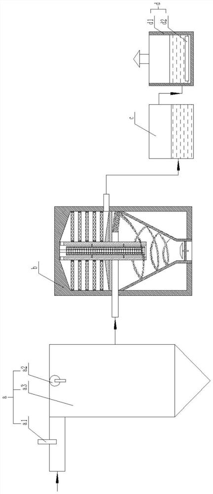
Industrial tail gas treatment system
A technology for treating system and industrial tail gas, which is applied in the direction of climate change adaptation, climate sustainability, chemical/physical process, etc. It can solve problems such as unsatisfactory single-stage treatment effect of tail gas, low emission requirements, unfulfilled emissions, etc., and achieve maintenance Low cost, improved bonding strength, and high dust collection efficiency
- Summary
- Abstract
- Description
- Claims
- Application Information
AI Technical Summary
Problems solved by technology
Method used
Image
Examples
Embodiment 1
[0020] The industrial tail gas treatment system includes a pretreatment unit a, a tail gas catalytic device b, a desulfurization device c, and a degreasing device d arranged sequentially along the direction of industrial waste gas transportation; the pretreatment unit a includes water mist generators connected in sequence device a1, charge generating device a2, aerosol mixing reactor a3, the desulfurization device c includes a pool body 1, and the water pool 1 is filled with saturated NaHCO 3 solution; the degreasing device d includes a pool body two d1, and several cooling pipes d2 are arranged in the pool body two d1;
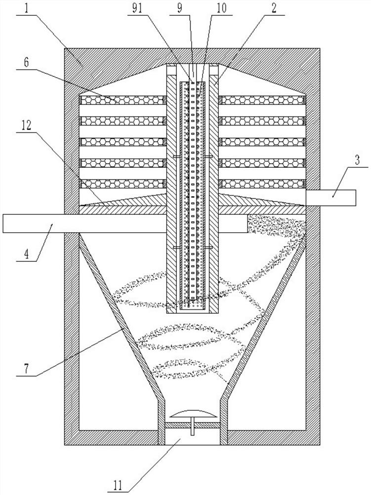
[0021] The tail gas catalytic device b includes a tower body 1, and the middle part of the tower body 1 is provided with a partition plate 12, and the partition plate 12 divides the tower body 1 into an upper catalytic purification area and a lower dust separation area, and the upper catalytic purification area The gas zone and the lower dust separation zone ...
Embodiment 2
[0023] The industrial tail gas treatment system includes a pretreatment unit a, a tail gas catalytic device b, a desulfurization device c, and a degreasing device d arranged sequentially along the direction of industrial waste gas transportation; the pretreatment unit a includes water mist generators connected in sequence device a1, charge generating device a2, aerosol mixing reactor a3, the desulfurization device c includes a pool body 1, and the water pool 1 is filled with saturated NaHCO 3solution; the degreasing device d includes a pool body two d1, and several cooling pipes d2 are arranged in the pool body two d1;
[0024] The tail gas catalytic device b includes a tower body 1, and the middle part of the tower body 1 is provided with a partition plate 12, and the partition plate 12 divides the tower body 1 into an upper catalytic purification area and a lower dust separation area, and the upper catalytic purification area The gas zone and the lower dust separation zone a...
Embodiment 3
[0027] The industrial tail gas treatment system includes a pretreatment unit a, a tail gas catalytic device b, a desulfurization device c, and a degreasing device d arranged sequentially along the direction of industrial waste gas transportation; the pretreatment unit a includes water mist generators connected in sequence device a1, charge generating device a2, aerosol mixing reactor a3, the desulfurization device c includes a pool body 1, and the water pool 1 is filled with saturated NaHCO 3 solution; the degreasing device d includes a pool body two d1, and several cooling pipes d2 are arranged in the pool body two d1;
[0028] The tail gas catalytic device b includes a tower body 1, and the middle part of the tower body 1 is provided with a partition plate 12, and the partition plate 12 divides the tower body 1 into an upper catalytic purification area and a lower dust separation area, and the upper catalytic purification area The gas zone and the lower dust separation zone ...
PUM
| Property | Measurement | Unit |
|---|---|---|
| denitrification rate | aaaaa | aaaaa |
| denitrification rate | aaaaa | aaaaa |
| denitrification rate | aaaaa | aaaaa |
Abstract
Description
Claims
Application Information
 - R&D
- Intellectual Property
- Life Sciences
- Materials
- Tech Scout
- Unparalleled Data Quality
- Higher Quality Content
- 60% Fewer Hallucinations
Browse by: Latest US Patents, China's latest patents, Technical Efficacy Thesaurus, Application Domain, Technology Topic, Popular Technical Reports.
© 2025 PatSnap. All rights reserved.Legal|Privacy policy|Modern Slavery Act Transparency Statement|Sitemap|About US| Contact US: help@patsnap.com


