Front grid line passivation contact-based PERC solar cell and preparation method thereof

A technology of solar cells and front grid lines, applied in circuits, photovoltaic power generation, electrical components, etc., can solve the problems of serious light parasitic absorption, battery short-circuit current loss, etc., to reduce carrier recombination, reduce body life and efficiency loss. , the effect of improving efficiency

Pending Publication Date: 2021-01-05
TRINA SOLAR CO LTD +1
View PDF8 Cites 6 Cited by
  • Summary
  • Abstract
  • Description
  • Claims
  • Application Information

AI Technical Summary

Problems solved by technology

However, due to the serious parasitic absorption of light by polysilicon, it will cause the short-circuit current loss of the battery.

Method used


Image

  • Front grid line passivation contact-based PERC solar cell and preparation method thereof

Examples


Embodiment 1

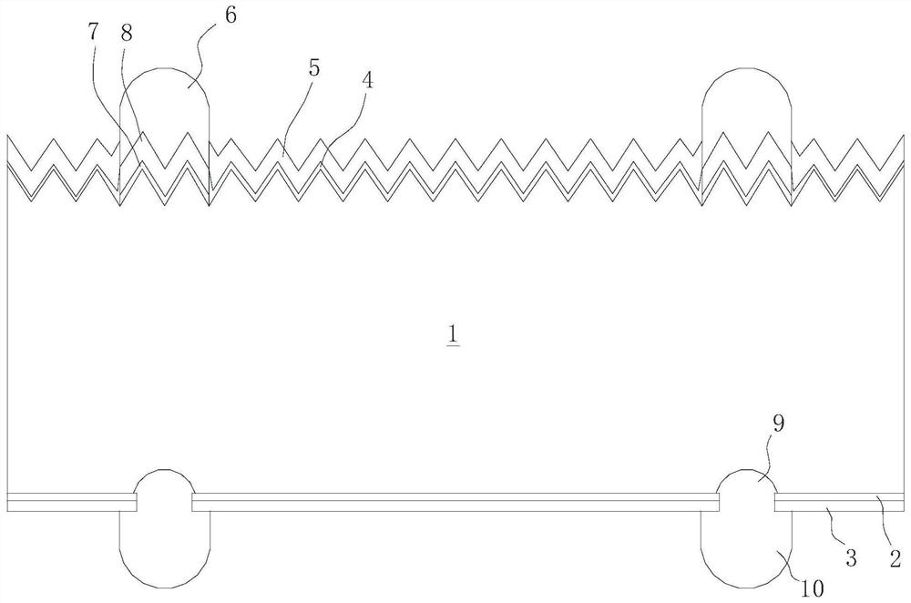
[0034] Such as figure 1 As shown, a PERC solar cell with passivation contact on the front gate line includes a P-type monocrystalline silicon substrate 1, and the back of the P-type monocrystalline silicon substrate 1 is sequentially provided with a back aluminum oxide passivation layer 2 and a back surface from the inside to the outside. Silicon nitride passivation layer 3, the front of P-type single crystal silicon substrate 1 is provided with front silicon oxide passivation layer 4 and front silicon nitride passivation layer 5 sequentially from inside to outside, and the front of P-type single crystal silicon substrate 1 is provided with There is a front metal silver grid line 6 that runs through the front silicon oxide passivation layer 4 and the front silicon nitride passivation layer 5, and it is characterized in that the front side of the P-type single crystal silicon substrate 1 is located on the front metal silver grid line 6 An ultra-thin tunneling silicon oxide laye...

Embodiment 2

[0040] A kind of preparation method of the PERC solar cell that the front grid line passivation contact of preparation embodiment 1 comprises the following steps,

[0041] 1) Texture making: use P-type monocrystalline silicon wafer as the substrate, place it in the texturing solution to make pyramid texture, and then clean the surface of the silicon wafer in a hydrofluoric acid solution with a volume concentration of 1-10% ,

[0042] 2) Preparation of ultra-thin tunneling silicon oxide layer: prepare a layer of ultra-thin tunneling silicon oxide on the front and back of the single crystal silicon substrate at the same time, the thickness of the tunneling silicon oxide is 1-2nm,

[0043] 3) Preparation of phosphorus-doped polysilicon layer: using LPCVD equipment to simultaneously deposit a layer of phosphorus-doped phosphorus-doped polysilicon layer on the ultra-thin tunneling silicon oxide on the front and back of the single crystal silicon substrate, with a thickness of 100-3...

Embodiment 3

[0053] A method for preparing the PERC solar cell with passivation contact on the front side of the gate line in Example 1, using a P-type single crystal silicon wafer as a substrate, and performing conventional texturing. After hydrofluoric acid and RCA standard cleaning, a layer of ultra-thin tunneling silicon oxide with a thickness of 1-2nm is simultaneously prepared on the front and back of the silicon substrate, and then a layer of ultra-thin tunneling silicon oxide is simultaneously deposited on the front and back of the silicon substrate by LPCVD equipment. Phosphorus-doped amorphous / microcrystalline silicon layer with a layer thickness of 100-300 nm. A mask is deposited on the front side of the silicon substrate by APCVD or PECVD, and then a corrosion-resistant ink consistent with the pattern of the front metal grid line is printed on the mask. The mask of the non-ink protection area is removed in a hydrofluoric acid solution with a volume concentration of 1-10%, and t...


PUM

PropertyMeasurementUnit
thicknessaaaaaaaaaa
thicknessaaaaaaaaaa
thicknessaaaaaaaaaa

Abstract

The invention belongs to the technical field of crystalline silicon solar cells, and relates to a front grid line passivation contact-basedPERC solar cell and a preparation method thereof. The solar cell comprises a P type monocrystalline silicon substrate; a back aluminum oxide passivation layer and a back silicon nitride passivation layer are sequentially arranged on the back surface of the P type monocrystalline silicon substrate from inside to outside. A front silicon oxide passivation layer and a front silicon nitride passivation layer are sequentially arranged on the front face of the Ptype monocrystalline silicon substrate from inside to outside; a front metal silver grid line penetrating through the front silicon oxide passivation layer and the front silicon nitride passivation layer is arranged on the front face of the P type monocrystalline silicon substrate. An ultrathin tunneling silicon oxide layer and a phosphorus-doped polycrystalline silicon layer are sequentially arranged on the front face of the P type monocrystalline silicon substrate and located below the front face metal silver grid line from inside to outside. According to the solar cell and preparation method thereof of the invention, the open-circuit voltage of the cell can be improved, the carrier recombination of a metal contact region can be reduced, the parasitic absorption of the doped polycrystalline silicon layer to light can be reduced, the current loss can be reduced, and the efficiency of the PERC cell can be improved.

Description

technical field [0001] The invention belongs to the technical field of crystalline silicon solar cells, and relates to a PERC solar cell and a preparation method thereof. Background technique [0002] In crystalline silicon solar cells, surface passivation is an important factor restricting efficiency. PERC (Passivated Emitter and Rear Cell), that is, passivated emitter and rear cell technology, was first proposed by Australian scientist Martin Green in 1983, and has now become a new generation of conventional technology for solar cells. PERC technology adds a fully covered passivation layer on the back of the cell to reduce back surface recombination and improve conversion efficiency, and then opens the passivation layer in the contact area through laser grooving to achieve metal contact. [0003] The advantages of PERC technology are also reflected in the fact that it can be superimposed with technologies such as multi-busbar, selective emitter and passivation contact to ...

Claims


Application Information

Patent Timeline
Patent Type & Authority Applications(China)
IPC IPC(8): H01L31/0224H01L31/0216H01L31/068H01L31/18
CPCH01L31/02167H01L31/022441H01L31/0682H01L31/1804H01L31/186H01L31/1864H01L31/1868Y02E10/546Y02E10/547Y02P70/50
Inventor 胡匀匀徐冠超冯志强张学玲杨阳安亦奇
Owner TRINA SOLAR CO LTD
Why Eureka
Try Eureka