Equalization circuit and control method based on bipolar t-type dual resonant switched capacitor converter
A technology of switching capacitors and balancing circuits, applied in charge balancing circuits, battery circuit devices, current collectors, etc., can solve problems such as slow balancing speed, and achieve the effects of reducing switching loss, realizing energy transmission, and shortening balancing time.
- Summary
- Abstract
- Description
- Claims
- Application Information
AI Technical Summary
Problems solved by technology
Method used
Image
Examples
Embodiment 1
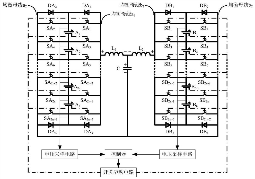
[0046] figure 1 It is an equalization circuit based on bipolar T-type dual-resonance switched capacitor converter suitable for 2*N cells, including two series battery packs, switch network, equalization bus, bipolar T-type dual-resonance switched capacitor converter, A switch driving circuit, a voltage sampling circuit and a controller, wherein the voltage sampling circuit collects the voltage signal of each battery cell and transmits it to the controller.
[0047] Two series-connected battery packs share a bipolar T-type dual-resonant switched capacitor converter for equalization. The series battery pack A is connected to the balancing bus a through the switch network A 1 and a 2 connected to the bipolar T-type double resonant switched capacitor converter; the series battery pack B is connected to the balanced bus bar B through the switch network B 1 and b 2 connected to the bipolar T-type dual-resonant switched capacitor converter.
[0048] The bipolar T-type dual reson...
Embodiment 2
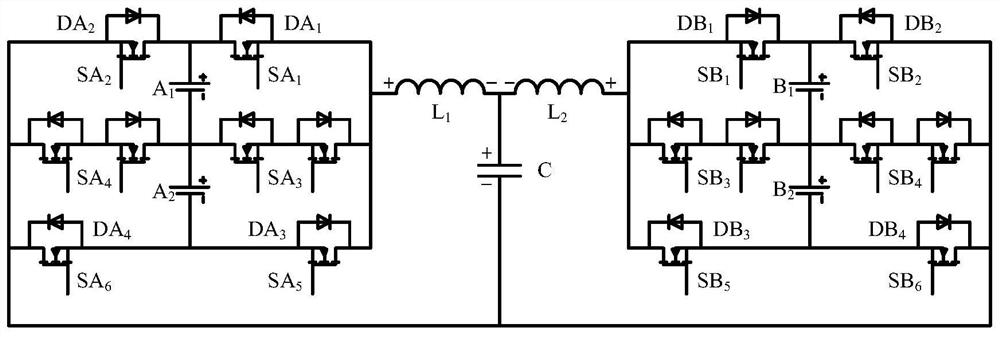
[0059] figure 2 It is an equalization circuit based on bipolar T-type dual resonant switched capacitor converter suitable for 2*2 cells. switch SA 1 , SA 2 , SA 5 , SA 6 and SB 1 , SB 2 , SB 5 , SB 6 Consists of an N-channel MOSFET. SA 1 (SB 1 ) and SA 5 (SB 5 ) D poles are respectively connected with battery A 1 (B 1 ) positive and A 2 (B 2 ) is connected to the negative pole, SA 1 (SB 1 ) and SA 5 (SB 5 ) of the S pole and the balanced bus a 1 (b 1 ) connection; SA 2 (SB 2 ) and SA 6 (SB 6 ) D poles are respectively connected with battery A 1 (B 1 ) positive and A 2 (B 2 ) is connected to the negative pole, SA 2 (SB 2 ) and SA 6 (SB 6 ) of the S pole and the balanced bus a 2 (b 2 )connect. switch SA 3 (SB 3 ) and SA 4 (SB 4 ) is composed of two N-channel MOSFETs connected in series with S poles, and the two ends are connected to battery A 1 (B 1 ) negative pole, balance bus a 1 (b 1 ) and battery A 1 (B 1 ) negative pole, balanc...
Embodiment 3
[0071] Assume that in the equalization circuit of the second embodiment, the battery voltage is VA 1 >VB 1 >VB 2 >VA 2 , after the voltage information of each battery cell is collected by the voltage sampling circuit, it is sent to the controller, and the controller judges A max -A min The value is the largest, then enter the balance mode 2, the energy from the battery A 1 pass to battery A 2 .
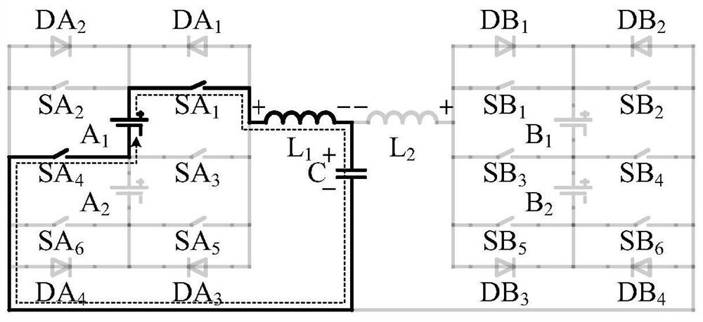
[0072] Figure 5is the direction of current flow during the equilibrium process, Image 6 is the corresponding theoretical waveform.
[0073] the positive state of charge of the capacitor, such as Figure 5 As shown in (a), the duration is t 0 'to t 1 '. at t 0 'moment, switch SA 1 and SA 4 on. battery A 1 through the inductance L 1 Charge the positive polarity of the capacitor C, the positive polarity of the capacitor voltage VC' rises, and the inductor current iL 1 ' Positive polarity rises and then falls to 0. at t 1 'moment, switch SA 1 and SA 4 Zero current...
PUM
 Abstract
Description
Claims
Application Information
 - R&D
- Intellectual Property
- Life Sciences
- Materials
- Tech Scout
- Unparalleled Data Quality
- Higher Quality Content
- 60% Fewer Hallucinations
Browse by: Latest US Patents, China's latest patents, Technical Efficacy Thesaurus, Application Domain, Technology Topic, Popular Technical Reports.
© 2025 PatSnap. All rights reserved.Legal|Privacy policy|Modern Slavery Act Transparency Statement|Sitemap|About US| Contact US: help@patsnap.com


