

Battery composite diaphragm, preparation method and application thereof
A composite diaphragm and battery technology, which is applied in the field of new energy batteries, can solve the problems of liquid absorption, poor liquid retention capacity, and low mechanical properties of the composite diaphragm, and achieve the effects of good liquid absorption, strong flame retardancy, and good thermal stability
- Summary
- Abstract
- Description
- Claims
- Application Information
AI Technical Summary
Problems solved by technology
Method used
Image

Examples
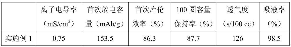
Embodiment 1
[0065] This embodiment provides a battery composite diaphragm, the preparation method of which is as follows:
[0066] (1) Mix PVDF Solef5130 and PVDF HSV900 with a mass ratio of 1:5 and N-methylpyrrolidone, heat in an oven at 55°C for 0.5h, and stir at 600rpm for 1h to obtain a solid content of 6%. PVDF glue;
[0067] (2) Under the rotating speed of 800rpm, Al with an average particle diameter D50 of 0.75 μm 2 o 3 Particles are added to the glue solution obtained in step (1), and after the addition is completed, stir for 4 hours at a speed of 1800rpm to obtain a slurry with a solid content of 24%, wherein Al 2 o 3 The mass ratio of particles to PVDF is 5:1, Al 2 o 3 The feeding rate of particles is 2g / min;
[0068] (3) After the slurry obtained in step (2) was left to stand for 8 hours, after cooling and defoaming, the slurry was coated on a glass plate with a thickness of 250 μm by a scraper, and placed in an oven at 50 ° C. After drying, it was soaked with ethanol an...
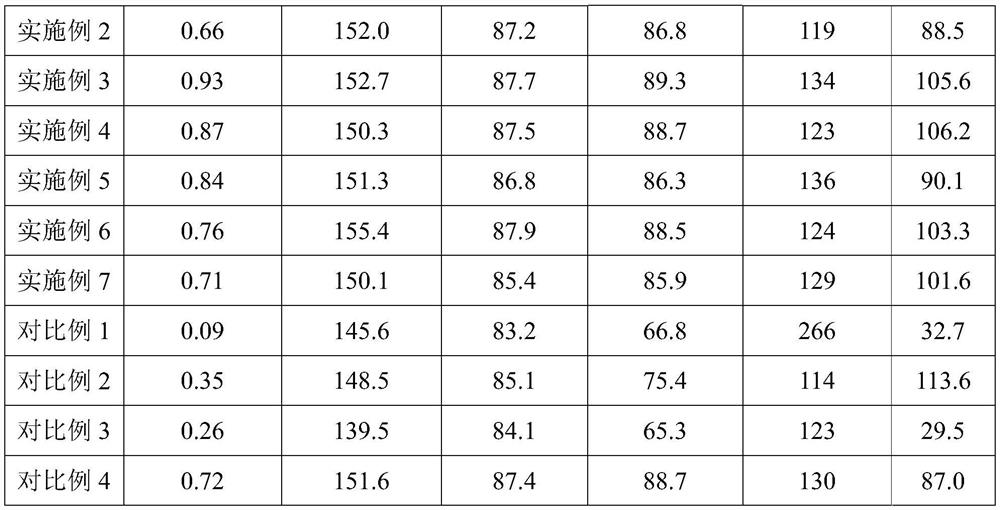
Embodiment 2
[0070] This embodiment provides a battery composite diaphragm, the preparation method of which is as follows:
[0071] (1) Mix PVDF Solef5130 and PVDF HSV900 with a mass ratio of 4:1 and N-methylpyrrolidone, heat in an oven at 60°C for 0.5h, and stir at 750rpm for 1h to obtain a solid content of 9%. PVDF glue;
[0072] (2) Under the rotating speed of 900rpm, Al with an average particle size D50 of 0.2 μm 2 o 3 Particles are added to the glue solution obtained in step (1). After the addition is completed, stir at a speed of 2500rpm for 4h to obtain a slurry with a solid content of 36%, wherein Al 2 o 3 The mass ratio of particles to PVDF is 3:1, Al 2 o 3 The feeding rate of particles is 3g / min;
[0073] (3) After the slurry obtained in step (2) was left to stand for 12 hours, after cooling and defoaming, the slurry was coated on a PET film with a thickness of 150 μm by a scraper, and placed in an oven at 70°C. After drying, tear off the mold directly to obtain a composit...
Embodiment 3
[0075] This embodiment provides a battery composite diaphragm, the preparation method of which is as follows:
[0076] (1) Mix PVDF Solef5130 and PVDF HSV900 with a mass ratio of 1:1 and N-methylpyrrolidone, heat in an oven at 60°C for 0.7h, and stir at 700rpm for 1h to obtain a solid content of 8%. PVDF glue;
[0077] (2) Under the rotating speed of 1000rpm, the average particle diameter D50 is 3μm Al 2 o 3 Particles are added to the glue solution obtained in step (1). After the addition is completed, stir at a speed of 1500rpm for 6h to obtain a slurry with a solid content of 31%, wherein Al 2 o 3 The mass ratio of particles to PVDF is 5:1, Al 2 o 3 The feeding rate of particles is 2.5g / min;
[0078] (3) After the slurry obtained in step (2) was left to stand for 10 hours, after cooling and defoaming, the slurry was coated on a glass plate with a thickness of 200 μm by a scraper, placed in an oven at 60 ° C, After drying, it was soaked with ethanol and released from t...
PUM
| Property | Measurement | Unit |
|---|---|---|
| thickness | aaaaa | aaaaa |
| particle diameter | aaaaa | aaaaa |
| thickness | aaaaa | aaaaa |
Abstract
Description
Claims
Application Information