Eureka AIR delivers breakthrough ideas for toughest innovation challenges, trusted by R&D personnel around the world.

EUV light source target drop generation device and method

A generation device and light source technology, which is applied in the direction of exposure devices, optics, and optomechanical equipment in the photographic plate-making process, can solve problems such as difficult to obtain droplets, irregular droplet sizes, and clogging, so as to improve energy conversion efficiency and improve use Efficiency and the effect of reducing manufacturing costs

Active Publication Date: 2021-01-29
ZHEJIANG UNIV
View PDF8 Cites 3 Cited by
  • Summary
  • Abstract
  • Description
  • Claims
  • Application Information

AI Technical Summary

Problems solved by technology

[0004] Patent CN 103064260A discloses a tin droplet target generating device used for the light source of extreme ultraviolet lithography machine, which uses the Rayleigh instability principle to generate target droplets, and then uses laser bombardment target droplets to obtain extreme ultraviolet light; if you want to obtain a smaller size If the target droplet is small, it is necessary to process smaller jet nozzle holes, which increases the difficulty of manufacturing, and easily causes problems such as clogging and excessive back pressure.
Patent CN 101279372A discloses a method and device for preparing microparticles by splitting droplets using the charge oscillation method. Disturbance is applied to the liquid jet to form droplets and charge the droplets, and high-frequency alternating current is applied to the charged droplets. Under the electric field, the charged droplets are split into larger main droplets and smaller microdroplets under the action of charge oscillation, but the size of the droplets produced by this scheme is irregular, and the sorting process is relatively complicated, and it is difficult to obtain enough flux of droplets

Method used


Image

  • EUV light source target drop generation device and method

Examples


Embodiment Construction

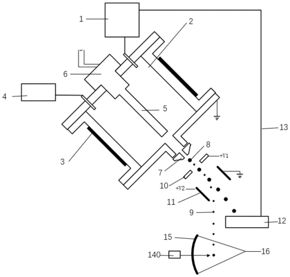
[0023] Such as figure 1 As shown, an EUV light source target droplet generating device includes a droplet generating component, a droplet separation component and a liquid recovery component; the droplet generating component is used to form droplets, and the droplet generating component includes: a storage tank 1 and a chamber 2 , a heating device 3 , a pressure source 4 , a disturbance rod 5 , a piezoelectric excitation module 6 and a microporous nozzle 7 . The storage tank 1 is used to store the material that forms the droplet. The storage tank 1 can store solid or liquid materials. The storage tank 1 can be provided with a heating device to keep the material in a molten state; the material in the storage tank 1 is supplied into the cavity 2. Under the heating effect of the heating device 3 provided on the outer wall of the chamber 2, it melts into a liquid state; the heating device 3 can be arranged inside or outside the chamber, and being arranged outside can avoid contact...


PUM

PropertyMeasurementUnit
Diameteraaaaaaaaaa

Abstract

The invention relates to an EUV light source target drop generation device and method. The device comprises a liquid drop generation assembly, a liquid drop separation assembly and a liquid recovery assembly, the liquid drop generation assembly comprises a storage tank, a containing cavity, a heating device, a pressure source, a shock excitation module, a disturbance rod and a micropore nozzle. The liquid drop separation assembly comprises a perforated electrode plate and a deflection electrode plate; and the liquid recovery assembly includes a liquid trap. Liquid drops are generated accordingto the Rayleigh instability principle, and the liquid drops with the proper size are sorted out to serve as target drops for laser bombardment of an EUV photoetching machine light source system. A target drop with an extremely small size can be obtained, and the energy conversion efficiency of laser bombardment on the target drop is improved; jet flow spray holes with large sizes can be used, sothat the manufacturing cost is reduced; and target drop materials are recycled repeatedly, the use efficiency is improved, and the cost is reduced.

Description

technical field [0001] The invention belongs to the technical field of droplet generating devices, and relates to an EUV light source target droplet generating device and method. Background technique [0002] The extreme ultraviolet lithography technology uses extreme ultraviolet light (Extreme Ultraviolet, EUV) with a wavelength of 13.5nm as a light source to expose the wafer, which can effectively improve the exposure resolution of the lithography machine and improve the performance of the integrated circuit. The existing extreme ultraviolet light generation technology adopts the laser-produced plasma (LPP) technology, that is, the continuous tin droplet (target droplet) is bombarded with a laser to make the target droplet plasma, and the target droplet plasma will produce extreme ultraviolet light. [0003] A method of generating continuous target droplets is based on the principle of Rayleigh instability of jets. First, liquid tin is sprayed to form jets, and a certain ...

Claims


Application Information

Patent Timeline
IPC IPC(8): G03F7/20H05G2/00
CPCG03F7/20G03F7/70033H05G2/006H05G2/008
Inventor 胡亮佘垒方言燊付新
Owner ZHEJIANG UNIV
Why Eureka
Eureka Blog
Learn More