Particle-stabilized foams using sustainable materials

A technology of foam and particles, applied in the direction of climate sustainability, sustainable waste treatment, ceramic material production, etc., can solve problems such as high carbon dioxide emissions and large amounts of surfactants

Pending Publication Date: 2021-02-05
ETH ZZURICH
View PDF12 Cites 5 Cited by
  • Summary
  • Abstract
  • Description
  • Claims
  • Application Information

AI Technical Summary

Problems solved by technology

These foams show high stability but also require large amounts of surfactants
Furthermore, during further processing of these foams, such as sintering, considerable CO2 emissions are formed

Method used


Image

  • Particle-stabilized foams using sustainable materials
  • Particle-stabilized foams using sustainable materials
  • Particle-stabilized foams using sustainable materials

Examples


Embodiment I

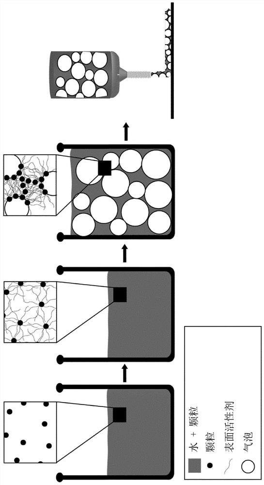
[0107] Example I: Mechanical foaming and addition of cement

[0108] Step 1: Optionally grinding the aluminosilicate particles obtained from the secondary raw material.

[0109] Step 2: Dissolve the long-chain surfactant in water.

[0110] Step 3: Add optionally milled aluminosilicate particles to the dissolved long-chain surfactant, with the particles dispersed by mixing at 200 rpm.

[0111] Step 4: Adjust the pH of the suspension in step 3 to a pH of 9-10.

[0112] Step 5: Foam the suspension obtained in step 4 using a high shear mixer at 800 to 1000 revolutions per minute.

[0113] Step 6: Disperse the cement in water.

[0114] Step 7: Mix the foamed suspension from step 4 and the cement dispersed in water from step 5 with a high shear mixer at 800 to 1000 rpm.

[0115] Step 8: Cast or extrude or 3D print the foamed suspension mixed in step 7.

[0116] Step 9: Make the foamed suspension cast or extruded or 3D printed in step 8 by covering or placing in a humidity cha...

Embodiment II

[0118] Example II: Mechanical Foaming and Addition of Alkali Solution

[0119] Step 1: Optionally grinding the aluminosilicate particles obtained from the secondary raw material.

[0120] Step 2: Dissolve the long-chain surfactant in water.

[0121] Step 3: Add optionally milled aluminosilicate particles to the dissolved long-chain surfactant, with the particles dispersed by mixing at 200 rpm.

[0122] Step 4: Adjust the pH of the suspension in step 3 to a pH of 9-10.

[0123] Step 5: Foam the suspension obtained in step 4 using a high shear mixer at 800 to 1000 revolutions per minute.

[0124] Step 6: To the foamed suspension obtained in step 5, sodium silicate solution (Na 2 O SiO 2 ), wherein the foamed suspension in step 5 is contained in one cartridge and the sodium silicate solution is contained in the other cartridge.

[0125] Step 7: Cast or extrude or 3D print the suspension mixed in step 6.

[0126] Step 8: Allow the mixed suspension cast or extruded or 3D pr...

Embodiment III

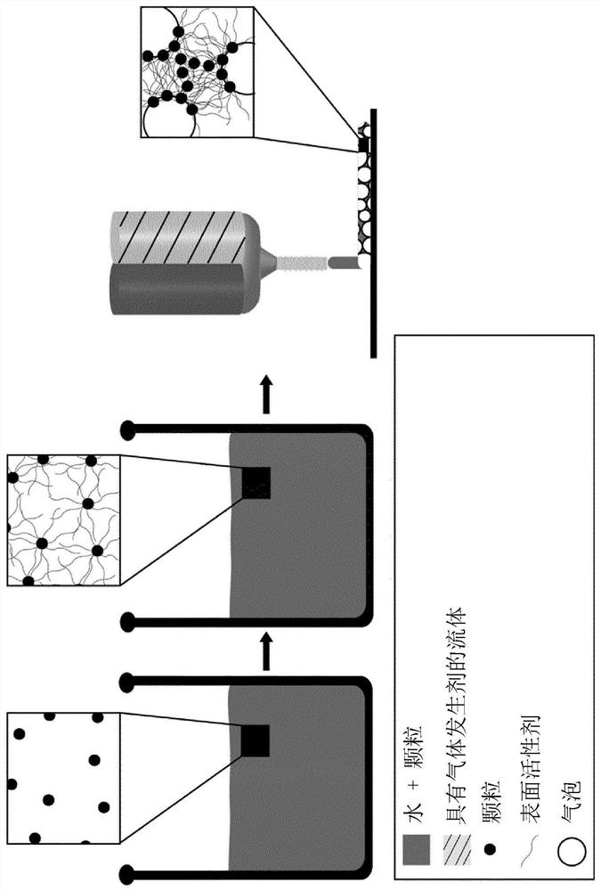
[0128] Example III: In Situ Foaming and Alkaline Solutions

[0129] Step 1: Optionally grinding the aluminosilicate particles obtained from the secondary raw material.

[0130] Step 2: Dissolve the long-chain surfactant in water.

[0131] Step 3: Add optionally milled aluminosilicate particles to the dissolved long chain surfactant.

[0132] Step 4: Adjust the pH of the suspension in step 3 to a pH of 9 to 10 and add a catalyst such as manganese oxide (MnO).

[0133] Step 5: Water and hydrogen peroxide (H 2 o 2 ) to prepare an alkaline solution.

[0134] Step 6: Mix the suspension from step 4 and the solution from step 5 using a twin static mixer with a single screw extruder.

[0135] Step 7: Cast or extrude or 3D print the suspension mixed in step 6.

[0136] Step 8: Allow the mixed suspension cast or extruded or 3D printed in step 7 to solidify by overlaying at 40 to 80°C, preferably 60°C for 24h.

[0137] Step 9: Drying the porous article in step 8.


PUM

PropertyMeasurementUnit
densityaaaaaaaaaa
sizeaaaaaaaaaa
densityaaaaaaaaaa

Abstract

Described is a method of preparing foams, wherein a suspension comprising an aqueous liquid, particles and at least one surfactant is provided, wherein the at least one surfactant at least partially hydrophobizes a surface of the particles, and wherein the suspension comprising the particles having the at least partially hydrophobized surface is foamed. The at least one surfactant is selected fromsurfactants having a backbone chain comprising at least nine carbon atoms, the at least one surfactant preferably being an amphiphilic molecule consisting of a tail coupled to a head group, wherein the tail comprises the backbone chain comprising at least nine carbon atoms.

Description

technical field [0001] The present invention relates to the field of foam formation. Background technique [0002] Modern insulation is expected to reduce total energy costs by 20% by 2030. However, today's modern solutions must also adapt to changing regulations, such as using non-flammable, non-toxic and environmentally friendly materials. Currently, many major industrial actors are unable to meet these requirements. Although made by toxic processes and highly flammable, polymer solutions such as expanded polystyrene (EPS) or polyurethane (PU) are most commonly used due to their low thermal conductivity. Other solutions, such as glass wool or mineral wool, are not flammable, but are energy-intensive to manufacture and can cause human health problems. Recent solutions such as porous cements or aerogels tend to achieve low thermal conductivity while being flame retardant and non-toxic during their manufacture. However, the former option is high in CO2 emissions, while ae...

Claims


Application Information

Patent Timeline
Patent Type & Authority Applications(China)
IPC IPC(8): C04B28/02C04B28/04C04B33/13C04B20/10C04B28/24C04B28/26C04B35/18
CPCC04B20/1022C04B20/1025C04B20/1048C04B28/02C04B28/04C04B28/24C04B28/26C04B33/132C04B33/135C04B35/18C04B35/6263C04B35/632C04B2111/00129C04B2111/00181C04B2235/3212C04B2235/3217C04B2235/3224C04B2235/3229C04B2235/3244C04B2235/3286C04B2235/3418C04B2235/441C04B2235/5409C04B2235/5445C04B2235/6026C04B2235/77C04B2235/96C04B2235/9607Y02P40/60Y02W30/91C04B14/041C04B24/08C04B38/10C04B2103/40C04B18/08C04B24/38C04B18/101C04B14/22
Inventor 安德烈·R·斯图亚特埃琳娜·埃莉沃特帕特里克·鲁斯乔纳斯·弗莱塔嘉莉贝蒂娜·泉恩茱莉亚·卡彭特克拉拉·米纳斯艾蒂安·杰弗罗伊
Owner ETH ZZURICH
Why Eureka
Try Eureka