
A deep heating cold end system for direct air cooling units

A technology of air-cooling units and air-cooling machines, applied in heating systems, space heating and ventilation, direct contact heat exchangers, etc., can solve problems such as difficult construction, unfavorable water saving, and large exhaust steam extraction pipelines, etc. Achieve enhanced safety and reliability, obvious energy-saving effects, and low space requirements

Active Publication Date: 2022-06-24
DONGFANG TURBINE CO LTD
View PDF6 Cites 0 Cited by
  • Summary
  • Abstract
  • Description
  • Claims
  • Application Information

AI Technical Summary

Problems solved by technology

[0005] Technical solution 2 adopts a newly added surface heat exchanger, and the steam drawn from the outlet steam pipe of the exhaust device is condensed in the external condenser; for example, the patent with the publication number CN109469522A discloses a exhaust steam cooling system and exhaust steam cooling system. Method, by setting a pipe connected to the inlet of the exhaust steam cooler on the exhaust pipe from the exhaust steam of the steam turbine to the air cooling island, during the zero output operation of the low pressure cylinder of the direct air cooling unit in the winter heating season, the steam distribution of the air cooling condenser is closed. All steam inlet valves are piped, the air-cooled condenser is isolated, and all the exhaust steam of the steam turbine unit is introduced into the exhaust steam condenser for condensation. The cooling water source is taken from the auxiliary cooling water system of the unit, and the condensed water is returned to the exhaust device of the main engine, completely solving the problem of direct air cooling The freezing problem of the air-cooled condenser during the heating operation of the low-pressure cylinder with zero output in the heating season of the unit; however, this solution has the following technical defects: due to the low steam pressure and large specific volume, the exhaust steam extraction pipeline is very large, the pipeline layout and civil engineering design The construction is difficult. At the same time, the circulating water of the condenser needs to be taken from the closed cooling water system or an independent closed circulating water system is installed. Usually, the direct air cooling unit area is seriously short of water. This solution needs to increase a large amount of circulating water, which is not conducive to water saving. And the system pipeline is complex, the failure rate is high during operation, and the investment is large

Method used


Image

  • A deep heating cold end system for direct air cooling units

Examples


Embodiment 1

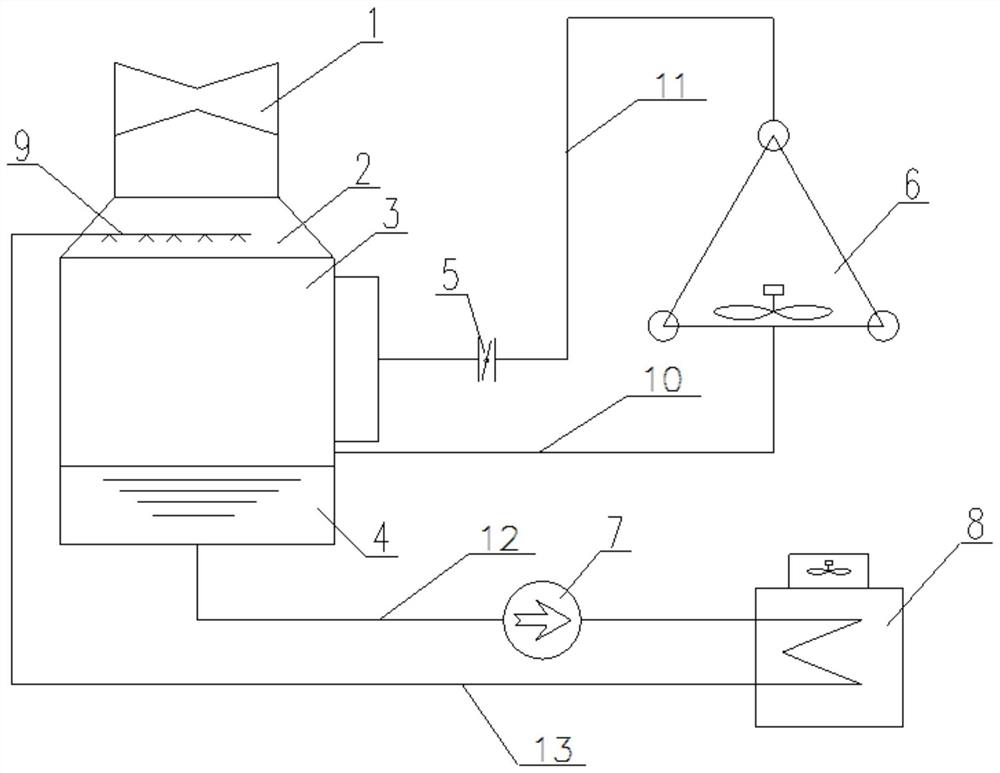
[0036] This embodiment is basically as figure 1Shown: This embodiment provides a direct air cooling unit deep heating cold end system, the system includes a low pressure cylinder 1, a steam exhaust device, a cooling water spray mechanism 9, an air cooling island 6 and an air cooling power tower 8, wherein the low pressure The cylinder 1 has an exhaust steam outlet for exhausting the exhaust steam of the steam turbine, and the exhaust steam device is connected with the exhaust steam outlet, so that the exhaust steam can enter the exhaust steam device; the cooling water spray mechanism 9 provided in this embodiment is arranged in the exhaust steam. In the device, so that the cooling water can exchange heat with the exhausted steam in the exhaust device and form condensed water.

[0037] Crucially, this embodiment provides a technical improvement in that the exhausted steam of the turbine is drawn out for condensation and water is used as the heat flow medium for cooling, that is...

Embodiment 2

[0041] The second embodiment is basically the same as the first embodiment, with the difference that: this embodiment provides a deep heating and cold end system for a direct air-cooled unit. The return line 11 connected with the steam exhaust device, so that the condensed water cooled by the air cooling island 6 can enter the steam exhaust device through the return line 11, and flow into the hot well of the steam exhaust device, so that the air cooling can be directly cooled in this embodiment. The condensed water cooled by the island 6 is introduced into the exhaust device for reheating, so as to achieve the purpose of reducing the oxygen content of the condensed water in the exhaust device.

Embodiment 3

[0043] The third embodiment is basically the same as the second embodiment, the difference is that: this embodiment provides a direct air-cooled unit deep heating cold end system, as the preferred embodiment of the second embodiment, the air-cooled power tower 8 provided in this embodiment is provided. It is equipped with a return pipe 2 13 connected to the steam exhaust device, so that the condensed water cooled by the air-cooling power tower 8 can enter the steam exhaust device through the return pipe 2 13, and flow into the steam exhaust device after mixing with the exhausted steam for heat exchange. In the hot well 4; at the same time, a condensate pump 7 is arranged on the drainage pipe 12 connected with the air-cooled power tower 8 and the steam exhaust device, so that the condensed water in the hot well 4 of the steam exhaust device can be discharged into the air-cooled power through the condensate pump 7 Tower 8.

[0044] Therefore, the design of the condensate pump 7 ...


PUM


Abstract

The invention discloses a deep heat supply cold end system of a direct air cooling unit, which relates to the technical field of the cold end of a steam turbine direct air cooling unit in a thermal power plant; it includes a low pressure cylinder, an exhaust device, a cooling water spray mechanism, an air cooling island and an air cooler The power tower, the exhaust device is connected to the exhaust outlet of the low pressure cylinder, the cooling water spray mechanism is arranged in the exhaust device, so that the cooling water can exchange heat with the exhaust steam in the exhaust device and form condensed water, and the air cooling island passes through The exhaust pipe is connected to the exhaust device, so that the exhaust steam in the exhaust device can be discharged into the air cooling island for cooling. An exhaust valve is arranged on the exhaust pipe, and the air cooling tower is connected to the exhaust device through the drain pipe. , so that the condensed water in the exhaust device can be discharged into the air-cooled power tower for cooling; through the implementation of this technical solution, it can effectively solve the problem of maintaining the low back pressure of the unit during the deep heating period and prevent the air-cooled island from appearing The risk of icing can effectively enhance the safety and reliability of the unit.

Description

technical field [0001] The invention relates to the technical field of the cold end of a direct air cooling unit of a steam turbine of a thermal power plant, in particular to a deep heating cold end system of a direct air cooling unit. Background technique [0002] In conventional thermal power direct air-cooled units undergoing deep heating transformation such as low-pressure cylinder cutting, micro-output, zero-output, etc., although the exhaust volume of the low-pressure cylinder is very small, it is also necessary to maintain the low back pressure of the steam turbine to reduce the final blade of the steam turbine. The risk of over-temperature of the blade brought by the blast, at the same time, the recovery is subject to some system leakage and the guarantee of the hydrophobic pressure difference. [0003] In the operation of the existing steam turbine, the exhaust steam of the steam turbine is condensed by entering the air-cooling island. Although the air-cooling islan...

Claims


Application Information

Patent Timeline
Patent Type & Authority Patents(China)
IPC IPC(8): F28C1/00F28F25/06F28B9/08F01K17/02F24D3/10
CPCF28C1/00F28F25/06F28B9/08F01K17/02F24D3/10
Inventor 阳欧高秀志周进颜强刘经武高晓亮姬艳云刘兴王泽锐
Owner DONGFANG TURBINE CO LTD
Learn More