Supercharge Your Innovation With Domain-Expert AI Agents!

Active clamp flyback converter, controller and control method thereof

A technology of flyback converter and control method, which is applied in the direction of control/regulation system, conversion of DC power input to DC power output, instruments, etc., can solve the problems of large no-load power consumption and low efficiency, and achieve the effect of excellent performance

Active Publication Date: 2021-03-16
MORNSUN GUANGZHOU SCI & TECH
View PDF9 Cites 2 Cited by
  • Summary
  • Abstract
  • Description
  • Claims
  • Application Information

AI Technical Summary

Problems solved by technology

[0006] In view of the deficiencies in the prior art, the technical problem to be solved by the present invention is to provide an active clamp flyback converter, a controller and its control method to solve the problem of low efficiency and no-load power consumption of the existing control mode at light load. The control problem of the conduction time of the first driving signal of the large and clamped switch tube

Method used


Image

  • Active clamp flyback converter, controller and control method thereof
  • Active clamp flyback converter, controller and control method thereof
  • Active clamp flyback converter, controller and control method thereof

Examples


no. 1 example

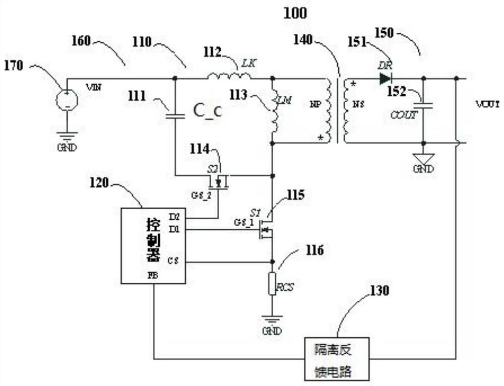
[0054] Please refer to figure 2 , figure 2 It is a schematic diagram of the active clamp flyback converter of the first embodiment of the present invention, the active clamp flyback converter 700 (hereinafter referred to as the converter) is used to convert the input voltage into an output voltage for use by the load , which includes: a transformer, a primary circuit, a secondary circuit, a controller 710 and an isolated feedback circuit 720 .

[0055] The primary winding NP of the transformer is connected to the primary circuit, and the secondary winding NS of the transformer is connected to the secondary circuit.

[0056] The primary side circuit is composed of leakage inductance LK, excitation inductance LM, clamp capacitor C_c, main switch S1, clamp switch S2, excitation inductance LM and current sampling resistor RCS. In this embodiment, the main switch tube S1 and the clamp switch tube S2 are respectively MOS tubes, the drain of the clamp switch S2 is connected to on...

no. 2 example

[0088] Please refer to Figure 9 , Figure 9 It is a schematic circuit diagram of an active clamp flyback converter according to the second embodiment of the present invention. Compared with Embodiment 1, in the embodiment, a resistor Rbleed is connected in parallel to both ends of the clamp capacitor C_c. Since this embodiment The clamp switch S2 is not driven at light load, that is to say, at light no-load, the converter 700 works in the flyback mode, but no matter what mode it works in, the energy on the leakage inductance LK always exists. Therefore, the leakage inductance LK energy will charge the clamping capacitor C_c through the body diode of the clamping switch S2. If the resistor Rbleed is not connected in parallel with the clamping capacitor C_c, the energy on the clamping capacitor C_c will accumulate. When the accumulation reaches a certain level The energy of the leakage inductance LK cannot be charged in, which will cause the converter 700 to work abnormally. T...


PUM


Abstract

The invention provides a controller of an active clamp flyback converter and a control method thereof, in the flyback converter, after the controller detects feedback voltage and compares the feedbackvoltage with set mode switching threshold voltage, switching between a double-pulse non-complementary mode and a leading-edge non-complementary mode is achieved, or switching between a double-pulse non-complementary mode and a flyback mode is carried out, the performance of the power supply system is better, and the six-level energy consumption requirement of the European Union is met; and compared with a trailing edge non-complementary mode, the double-pulse non-complementary mode has the advantages that after the main switch tube is turned off, the leakage inductance and the clamping capacitor resonance are realized through the clamping switch tube instead of a body diode of the clamping switch tube, so that the problem of reverse recovery of the body diode of the clamping switch tube is solved. The conduction time of the first double-pulse non-complementary pulse signal is controllable and is 1 / 4 of the resonance period of the clamping capacitor and the leakage inductor, so that the problem of reverse recovery is solved, the leakage inductor is prevented from being reversely charged after the resonance current crosses zero, and the EMI problem of the converter is improved.

Description

technical field [0001] The invention relates to the field of switching power supply design, in particular to an active clamp flyback converter, a controller and a control method thereof. Background technique [0002] Flyback converters are widely used in small and medium power switching power supplies because of their low cost and simple topology. In the actual working process, due to the existence of the leakage inductance of the flyback converter, the energy of the primary side cannot be completely transferred to the secondary side, and the resonance between the leakage inductance energy left on the primary side and the junction capacitance of the MOS tube causes the drain of the main switch tube Generate high frequency voltage spikes. In the process of product design, in order to reduce the voltage stress of the switch tube, it is common practice to add suitable snubber circuits. Common snubber circuits include RCD snubber circuits, LCD snubber circuits and active clamp ...

Claims


Application Information

Patent Timeline
IPC IPC(8): H02M1/08H02M3/335
CPCH02M1/08H02M1/083H02M3/33523
Inventor 王海洲
Owner MORNSUN GUANGZHOU SCI & TECH
Features
  • R&D
  • Intellectual Property
  • Life Sciences
  • Materials
  • Tech Scout
  • Unparalleled Data Quality
  • Higher Quality Content
  • 60% Fewer Hallucinations
Learn More