Laser shield tunneling machine and tunneling method

A technology of shield machine and laser, which is applied in the direction of earth drilling, mining equipment, tunnels, etc., can solve the problems of single and incomplete experimental performance, and achieve the effects of reducing wear, improving efficiency, and improving tunneling efficiency

Pending Publication Date: 2021-03-23
LASER FUSION RES CENT CHINA ACAD OF ENG PHYSICS
View PDF9 Cites 0 Cited by
  • Summary
  • Abstract
  • Description
  • Claims
  • Application Information

AI Technical Summary

Problems solved by technology

[0006] However, at present, there are still relatively large technical difficulties in laser rock breaking, and simulation experiments are mainly carried out in the laboratory. However, the experimental equipment required for theoretical research on laser rock breaking is not complete, and the existing experimental systems generally use fixed laser irradiation. The method has the disadvantage of single experimental performance, and cannot effectively cooperate with the tunneling device to achieve the purpose of rapid tunneling

Method used


Image

  • Laser shield tunneling machine and tunneling method
  • Laser shield tunneling machine and tunneling method
  • Laser shield tunneling machine and tunneling method

Examples


specific Embodiment 1

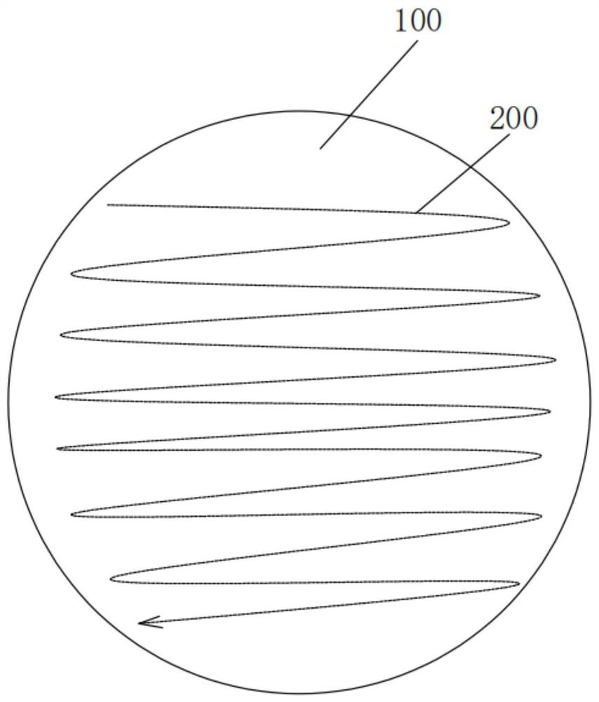
[0035] A laser shield machine, see Figure 1-2 , which includes a laser perforating device for perforating the working face 100, and a tunneling device for excavating the working face 100 after perforating by the laser perforating device. The laser perforating device and the tunneling device are of a separate structure.

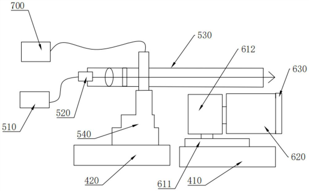
[0036] Further, at least one laser perforating device is provided. The laser perforating device includes a laser 510, a laser output head 520, and a shooting barrel 530 connected to the output end of the laser output head 520 for protecting the laser channel. The laser 510 and the laser output head 520 pass through. The laser line is connected, and the optical axis of the laser beam output by the laser output head 520 coincides with the central axis of the shooting cylinder 530. The end of the shooting cylinder 530 is provided with a first laser hole for realizing the transmission of the laser beam to the working surface 100. A laser channel for laser beam tr...

specific Embodiment 2

[0051] The same places in this embodiment and specific embodiment 1 will not be repeated, and the differences are as follows:

[0052] Using multiple light sources and multiple shooting cylinders to perforate at the same time can be realized by two structures, specifically:

[0053] One is that one laser corresponds to multiple barrels, and the laser beam emitted by the laser is provided with a laser beam splitter. The laser beam splitter is a high-power laser beam splitter, which divides the laser into multiple beams. One-to-one correspondence of shooting cylinders to achieve the purpose of simultaneous perforation of multiple light sources and multiple shooting cylinders; the other is that multiple lasers correspond to multiple laser output heads and shooting cylinders, so as to realize the simultaneous perforation of multiple light sources corresponding to multiple shooting cylinders. Purpose.

[0054] Specifically, each shooting barrel is integrated into a whole, and the ...

specific Embodiment 3

[0056] The same places in this embodiment as in specific embodiment 1 and specific embodiment 2 will not be repeated, and the differences are as follows:

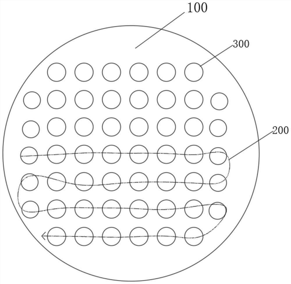
[0057] The laser perforating device and the tunneling device have an integrated structure. The shooting barrel 530 is integrated inside the rotating drum. A beam splitter connected to the laser output head is arranged in the shooting barrel 530. The beam splitter splits the laser output from the laser output head 520. For multiple beams, the first laser hole is provided with a plurality of laser beams, the drill bit 630 is provided with a second laser hole corresponding to each first laser hole, and the laser output head emits laser light through the first laser hole and the second laser hole. noodle.

[0058] Preferably, the second laser holes are evenly arranged on the upper surface of the drill bit.

[0059] A driving method using the above-mentioned laser shield machine is to pre-break the rock at the working face thro...


PUM


Abstract

The invention discloses a laser shield tunneling machine and a tunneling method. The laser shield tunneling machine comprises a laser perforating device and a tunneling device, wherein the laser perforating device is used for perforating a working face, the tunneling device is used for tunneling the working face perforated by the laser perforating device, and the laser perforating device and the tunneling device are of an integrated structure or a split structure. According to the laser shield tunneling machine and the tunneling method, rock array type perforation is conducted through the laser perforating device, working face rock is pre-crushed, the drillability of the working face rock is improved, tunneling is conducted through the tunneling device, the tunneling efficiency is improvedunder the condition that the rock strength is reduced, meanwhile, abrasion of a drill bit is reduced, molten slag in a jetting barrel is blown away through compressed air, a laser output head can bewell protected, the single-light-source multi-machining-head can be adopted for parallel perforation in a light source rapid switching mode, or the multi-light-source multi-machining-head can be adopted for simultaneous perforation, and the tunneling efficiency is further improved.

Description

technical field [0001] The invention belongs to the technical field of laser rock breaking application, and in particular relates to a laser shield machine and an excavation method. Background technique [0002] During the excavation of large-scale tunnels, especially in the mountains and deep underground, there are rock layers, especially hard rock layers such as basalt, which make the excavation speed relatively slow. [0003] In the prior art, blasting demolition and direct excavation by roadheaders are usually used. Among them, the excavation method of blasting and demolition has problems in the control of pyrotechnics, safety problems and cost problems. At the same time, the controllability of the working face is poor, and the excavation efficiency is low. However, the direct excavation method of the roadheader uses teeth to directly crush and excavate the rock formation, so that the excavation efficiency is low and the loss of the drill bit is high. [0004] like fi...

Claims


Application Information

Patent Timeline
Patent Type & Authority Applications(China)
IPC IPC(8): E21D9/10
CPCE21D9/1073
Inventor 朱启华康民强邓颖粟敬钦黄醒董一方周松蒋学君李剑彬向祥军张帆郑建刚郑奎兴陈波郑万国
Owner LASER FUSION RES CENT CHINA ACAD OF ENG PHYSICS
Why Eureka
Try Eureka