Integrated device and process for solar cell film coating and light injection

A technology for solar cells and integrated equipment, applied in the field of solar cells, can solve problems such as the decrease in the bonding strength between silver wires and silicon chips, the adverse effects of cell yields, and the increase in battery manufacturing costs, and solve the problems of reduced bonding strength, Easy optimization of curing conditions and reduced manufacturing costs

Pending Publication Date: 2021-03-30
CHANGZHOU BITAI TECH
View PDF0 Cites 2 Cited by
  • Summary
  • Abstract
  • Description
  • Claims
  • Application Information

AI Technical Summary

Problems solved by technology

[0009] 1. From the perspective of technology, the battery with the above structure can generate power at the same time on both sides after it is formed. It is a natural double-sided battery with high power generation efficiency, and the highest power generation efficiency can reach more than 25%. However, HIT double-sided battery The disadvantage is that the conductive silver paste must be cured at a temperature below 200°C for about 30 minutes. Therefore, low-temperature silver paste must be used, but the optimum temperature for light injection is above 200°C. If the silicon wafer is injected with light after printing silver lines, Its process temperature higher than 200°C will inevitably lead to a rapid decrease in the bonding strength between the silver wire and the silicon wafer;
[0010] 2. From a production point of view, in the battery manufacturing process, adding an independent device to complete the light injection means adding a new battery manufacturing process in the HIT process, and at the same time, additional equipment investment is increased, and the battery manufacturing cost is also increased. ; In addition, it will also involve the turnover of silicon wafer loading and unloading, equipment maintenance and other issues, which will inevitably lead to increased labor costs and low production efficiency, and the extension of the battery process cycle will also adversely affect the battery yield.

Method used


Image

  • Integrated device and process for solar cell film coating and light injection

Examples


Embodiment Construction

[0035] The following will clearly and completely describe the technical solutions in the embodiments of the present invention with reference to the drawings in the embodiments of the present invention.

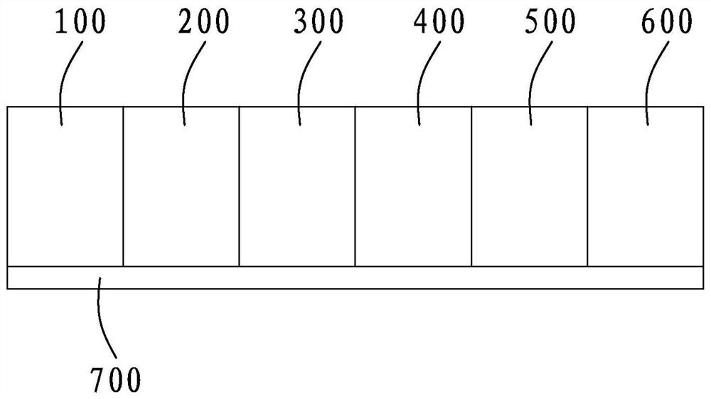
[0036] refer to figure 1 , the present invention provides an integrated device for solar cell film coating and light injection, including a TCO coating chamber 300 and a light injection annealing chamber 400 arranged in sequence, corresponding to the chain transmission of the TCO coating chamber 300 and the light injection annealing chamber 400 The conveying mechanism, and the carrier plate used for carrying silicon wafers that are arranged on the conveying mechanism in a flat manner; the feed end of the TCO coating chamber 300 is also provided with a loading vacuum chamber 200, and the discharge end of the light injection annealing chamber 400 is also provided with There is an unloading vacuum chamber 500; the feeding end of the loading vacuum chamber 200 is also provided wit...


PUM


Abstract

The invention discloses an integrated device and process for solar cell film coating and light injection. The integrated device comprises a silicon wafer feeding mechanism, a chain type conveying mechanism and a light injection mechanism, wherein the silicon wafer feeding mechanism is used for horizontally placing a silicon wafer on a flat carrier plate for feeding, and the carrier plate is conveyed by the chain type conveying mechanism to enter a loading vacuum cavity; the carrier plate enters the TCO coating cavity for TCO coating; the carrier plate enters the light injection annealing cavity for light injection annealing; the carrier plate enters the unloading vacuum cavity for atmospheric backfilling; a silicon wafer discharging mechanism is adopted to discharge the silicon wafer; andthe empty carrier plate is returned to the feeding end through the carrier plate swing mechanism. According to the invention, two processes of TCO coating and light injection annealing are integratedin one piece of equipment, the chain-type continuous operation is realized by utilizing the flat-lying carrier plate, and the light injection annealing is firstly finished before the silver wire is printed, so that the process integration degree is high, the equipment investment is reduced, the process period is shortened, the production efficiency and the product yield are improved, and the battery manufacturing cost is reduced accordingly; the problem that the bonding strength of the silver wire and the silicon wafer is reduced due to the light injection annealing process in the prior art issolved.

Description

technical field [0001] The invention relates to the technical field of solar cells, in particular to an integrated device and process for solar cell film coating and light injection. Background technique [0002] Photovoltaic power generation has become a technology that can replace fossil energy, which relies on the continuous reduction of production costs and the improvement of photoelectric conversion efficiency in recent years. According to the material of photovoltaic cells, solar cells can be roughly divided into two categories: one is crystalline silicon solar cells, including monocrystalline silicon solar cells and polycrystalline silicon solar cells; the other is thin-film solar cells, mainly including amorphous silicon solar cells , cadmium telluride solar cells and copper indium gallium selenide solar cells. At present, crystalline silicon solar cells with high-purity silicon as the main raw material are the mainstream products, accounting for more than 80%. [...

Claims


Application Information

Patent Timeline
Patent Type & Authority Applications(China)
IPC IPC(8): H01L31/18H01L21/677
CPCH01L21/67742H01L21/67745H01L21/6776H01L31/186H01L31/1864H01L31/1876Y02E10/50Y02P70/50
Inventor 上官泉元邹开峰
Owner CHANGZHOU BITAI TECH
Why Eureka
Try Eureka