
Evaporative cooling type laser

An evaporative cooling and laser technology, applied in the field of lasers, can solve the problems of condensation on the surface of the device, high energy consumption of refrigeration units, poor portability, etc., and achieve the effects of reducing investment costs, low operating costs, and high heat exchange efficiency.

Pending Publication Date: 2021-03-30
北京同方华光系统科技有限公司
View PDF0 Cites 0 Cited by
  • Summary
  • Abstract
  • Description
  • Claims
  • Application Information

AI Technical Summary

Problems solved by technology

This cooling method has the following disadvantages: first, the use of chillers will increase the input cost of the entire laser processing system; second, the high energy consumption of the refrigeration unit will increase the operating cost of the entire laser processing system; In the environment, it is easy to cause condensation on the surface of the device during actual operation, thereby increasing the risk of system failure
At present, there is also a laser that dissipates heat through a water-cooled method without a compressor. This method uses a water pump to transport the heat of the laser to the condenser (liquid-gas heat exchanger) with a liquid, and then exchanges sensible heat with air. The disadvantages include : 1. The whole system is a split design, the light source and the condenser are separated in space, and the portability is poor; 2. There is sensible heat exchange between the condenser and the air, and even the ideal temperature of the liquid will not be lower than the dry bulb of the air temperature, so cannot accommodate higher power lasers

Method used


Image

  • Evaporative cooling type laser
  • Evaporative cooling type laser

Examples


Embodiment Construction

[0034] In order to make the above objects, features and advantages of the present invention more apparent, exemplary embodiments of the present invention will be described in more detail below with reference to the accompanying drawings. Although exemplary embodiments of the present invention are shown in the drawings, it should be understood that the invention may be embodied in various forms and should not be limited to the embodiments set forth herein. Rather, these embodiments are provided for more thorough understanding of the present invention and to fully convey the scope of the present invention to those skilled in the art.

[0035] The idea of ​​the present invention is to propose an evaporative cooling laser system, which utilizes heat pipes or other high thermal conductivity materials to convert the laser After the heat is exported to the heat dissipation unit, pour liquid on the heat dissipation surface of the heat dissipation unit, and use the effect of liquid eva...


PUM


Abstract

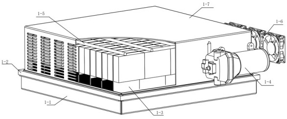
The invention discloses an evaporative cooling type laser which comprises a laser light source part, a laser mounting base, a heat dissipation unit, a water pump, a water distribution pipeline, a heatdissipation fan and a shell. The water distribution pipeline is connected with the micro water pump, a bottom pipeline serves a water pump suction inlet, and a top pipeline is connected with a waterpump outlet. The laser has the advantages that a refrigeration compressor is not needed, and the investment cost is reduced; a natural cold source heat dissipation mode is adopted, so that the operation cost is lower; through an evaporative cooling mode, total heat exchange of sensible heat and latent heat between a heat source and air is achieved, the heat exchange efficiency is higher, and the device can adapt to lasers with higher power; and an in-situ heat pipe is adopted for heat conduction, heat starts to be subjected to total heat exchange with air after being transmitted to the turbulent flow metal body in a short distance, heat does not need to be transmitted remotely, and the whole machine structure is more compact.

Description

technical field [0001] The invention relates to the field of lasers, in particular to a semiconductor laser and a fiber laser capable of realizing low power consumption operation. Background technique [0002] Compared with the traditional machining process, laser processing has the characteristics of high efficiency and high precision. For laser cutting, cladding and welding systems, a stable and reliable laser light source is very important, and one of the necessary conditions for the reliable operation of the laser light source is a good thermal management. At present, the common laser thermal management method is to use a chiller with a refrigeration compressor as a cooling source, and take away the heat of each device inside the laser through water cooling. This cooling method has the following disadvantages: first, the use of chillers will increase the input cost of the entire laser processing system; second, the high energy consumption of the refrigeration unit will ...

Claims


Application Information

Patent Timeline
Patent Type & Authority Applications(China)
IPC IPC(8): H01S3/04H01S5/024
CPCH01S3/04H01S3/0405H01S3/0407H01S5/02415H01S5/02423H01S5/02469H01S5/02484
Inventor 唐晟廖素英周鹏磊王安敏耿伟豪
Owner 北京同方华光系统科技有限公司
Learn More