Preparation method of heat-resisting plate for bias plate

A heat-resistant plate and deflector technology, applied in the field of deflectors, can solve the problems of reducing the thermal conductivity of deflectors, reducing the weight of deflectors, and high thermal conductivity, and achieving the effects of reducing maintenance costs, weight, and thermal conductivity.

Active Publication Date: 2021-04-16
GONG YI VAN-RES INNOVATION COMPOSITE MATERIAL CO LTD
View PDF6 Cites 1 Cited by
  • Summary
  • Abstract
  • Description
  • Claims
  • Application Information

AI Technical Summary

Problems solved by technology

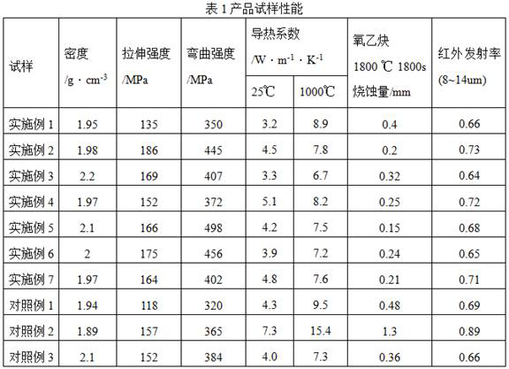
[0007] In order to overcome the deficiencies of poor corrosion resistance, short life, and high thermal conductivity of the deflector plate, the purpose of the present invention is to provide a method for preparing a heat-resistant plate for the deflector plate. The present invention uses carbon fiber reinforced ceramic matrix composite material, The weight of the deflector can be greatly reduced, and the thermal conductivity of the deflector can be reduced; the present invention uses chemical vapor infiltration to prepare a pyrolytic carbon interface layer with a thickness of 1-2 μm, which is relatively thick, and the interface layer is uniform and continuous, and tends to be smooth. , the toughening effect is good, the interface layer is a continuous layered structure, and the combination with carbon fibers is good, which can effectively avoid the cracks that cannot be deflected at the interface and cross the fibers due to the strong bonding interface effect; use high and low temperature cycle impregnation-cracking process, improve the impregnation efficiency, reduce the production cycle, and thus reduce the cost; the introduction of nano-ceramic powder into the precursor slurry can greatly improve the sealing efficiency, improve the high temperature resistance, seawater corrosion resistance, erosion resistance and oxidation resistance of the material, Extended service life

Method used


Image

  • Preparation method of heat-resisting plate for bias plate

Examples


Embodiment 1

[0049] A method for preparing a heat-resistant plate used for a deflector plate, the steps are as follows:

[0050] (1) Processing carbon fiber prefabricated body: choose 2.5D thin edge puncture to make the density of 0.5g / cm 3 The carbon fiber prefabricated body; the carbon fiber prefabricated body is processed into a prefabricated body with the same shape as the final heat-resistant plate product and a large margin in size;

[0051] (2) CVI deposited pyrolytic carbon interface layer: clamp and fix the preform obtained in step (1) with a graphite mold designed according to the structure of the preform, put the preform with the mold into the CVI deposition furnace, and evacuate to The vacuum degree in the furnace is 100Pa, then the temperature is raised to 1000°C, and then the carbon source gas propane is introduced at a flow rate of 10L / min, the pressure in the furnace is controlled at 5kPa, and the temperature is kept for 25h; Naturally cool down to room temperature under a...

Embodiment 2

[0071] A method for preparing a heat-resistant plate used for a deflector plate, the steps are as follows:

[0072] (1) Processing carbon fiber prefabricated body: choose 2.5D0° / 90° no-weft lamination / net tire needle punching to obtain a density of 0.55g / cm 3 The carbon fiber prefabricated body; the carbon fiber prefabricated body is processed into a prefabricated body with the same shape as the final heat-resistant plate product and a large margin in size;

[0073] (2) CVI deposited pyrolytic carbon interface layer: clamp and fix the preform obtained in step (1) with a graphite mold designed according to the structure of the preform, put the preform with the mold into the CVI deposition furnace, and evacuate to The vacuum degree in the furnace is 100Pa, and then the temperature is raised to 1300°C, and then the carbon source gas methane is introduced at a flow rate of 15L / min, the pressure in the furnace is controlled at 13kPa, and the temperature is kept for 50h; Naturally ...

Embodiment 3

[0094] A method for preparing a heat-resistant plate used for a deflector plate, the steps are as follows:

[0095] (1) Processing carbon fiber prefabricated body: use 3D carbon fiber weaving and molding to obtain a density of 0.45g / cm 3 The carbon fiber prefabricated body; the carbon fiber prefabricated body is processed into a prefabricated body with the same shape as the final heat-resistant plate product and a large margin in size;

[0096] (2) CVI deposited pyrolytic carbon interface layer: clamp and fix the preform obtained in step (1) with a graphite mold designed according to the structure of the preform, put the preform with the mold into the CVI deposition furnace, and evacuate to The vacuum degree in the furnace is 200Pa, and then the temperature is raised to 1070°C, and then the carbon source gas natural gas is introduced at a flow rate of 12L / min, the pressure in the furnace is controlled at 12kPa, and the temperature is maintained for 50h; Naturally cool down to...


PUM

PropertyMeasurementUnit
densityaaaaaaaaaa
thicknessaaaaaaaaaa
densityaaaaaaaaaa

Abstract

The invention belongs to the technical field of bias plates, and discloses a preparation method of a heat-resisting plate for a bias plate. The method comprises the following steps: (1) processing a carbon fiber preform according to the structure of a heat-resistant plate; (2) preparing a pyrolytic carbon interface layer on the surface of the carbon fiber preform by a CVI method; (3) repeating the steps of dipping, curing and low-temperature cracking for 2-4 times; (4) repeating the steps of dipping, curing and high-temperature cracking for 1-3 times; (5) carrying out mechanical rough machining; (6) repeating the steps of dipping, curing and low-temperature cracking for 2-4 times; (7) repeating the steps of dipping, curing and high-temperature cracking for 1-3 times; (8) carrying out mechanical finish machining; and (9) depositing a SiC coating by using a CVD method to obtain the heat-resistant plate for the bias plate. The method is short in preparation period, and the prepared heat-resisting plate is high in density, small in density gradient, extremely low in ablation rate, low in emissivity, good in oxidation resistance and scouring resistance and excellent in mechanical property.

Description

technical field [0001] The invention belongs to the technical field of deflector plates, and in particular relates to a method for preparing a heat-resistant plate used for deflector plates. Background technique [0002] The deflector deflects the high-temperature, high-pressure, and high-speed gas flow generated by the aircraft engine on the aircraft carrier to the outside, preventing the tail flame from threatening the aircraft carrier's equipment, other aircraft and personnel. The heat-resistant plate is the upper panel where the deflector plate is in direct contact with the exhaust flame of the engine. It mainly bears the scouring force of the aircraft exhaust flame and deflects the fuel flow in all directions. It is required to have high temperature resistance, seawater corrosion resistance, ablation resistance, and erosion resistance. . [0003] At present, metal materials are generally used for deflectors, and coatings with heat resistance and heat dissipation proper...

Claims


Application Information

Patent Timeline
Patent Type & Authority Applications(China)
IPC IPC(8): C04B35/83C04B35/52C04B35/622B64F1/26
Inventor 张东生吴恒马美霞姚栋嘉刘喜宗张相国潘广镇董会娜
Owner GONG YI VAN-RES INNOVATION COMPOSITE MATERIAL CO LTD
Why Eureka
Try Eureka