Circuit for triggering excimer laser to generate plasma
An excimer laser and plasma technology, which is applied to lasers, phonon exciters, laser parts, etc., can solve the problem that high-voltage pulse signals do not have fast frontiers, reduce the performance of excimer lasers, and cannot achieve time synchronization of excimer lasers. And other issues
- Summary
- Abstract
- Description
- Claims
- Application Information
AI Technical Summary
Problems solved by technology
Method used
Image
Examples
Embodiment 1
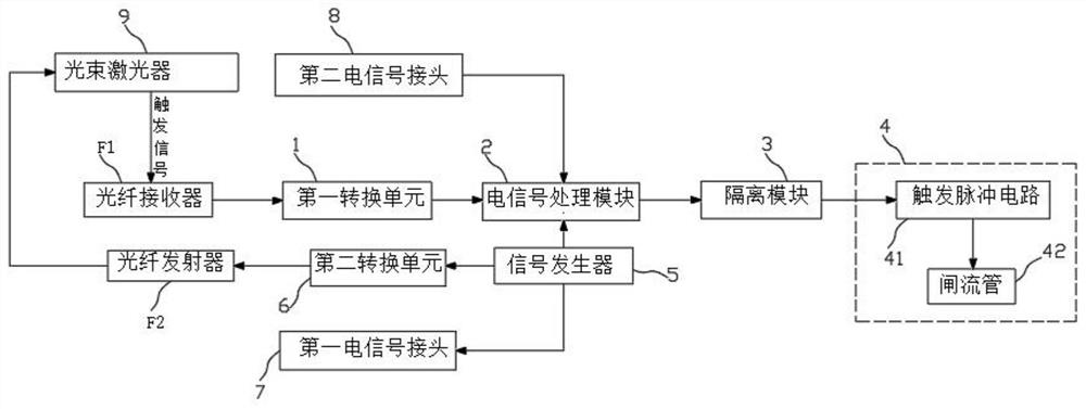
[0057] A device for triggering an excimer laser, the device comprising the following components:
[0058] A signal acquisition module, used for collecting the trigger signal of the beam laser 9 that sends the seed light to the gas laser 4;
[0059] The electrical signal processing module 2 is used to receive and process the trigger signal of the beam laser 9 collected by the signal acquisition module, and input the processed trigger signal to the enabling terminal of the gas laser 4, so that the time when the seed light reaches the gas laser 4 It is synchronized with the discharge time of the gas laser 4; the discharge time of the gas laser 4 is controlled by the enabling terminal of the gas laser 4.
[0060] The signal acquisition module includes a fiber optic receiver F1 and a first conversion unit 1; the trigger signal of the beam laser 9 is input to the photoresistor of the fiber optic receiver F1 in the form of an optical signal; The input end is electrically connected, ...
Embodiment 2
[0078] In the basic line of embodiment 1, it is introduced respectively below:
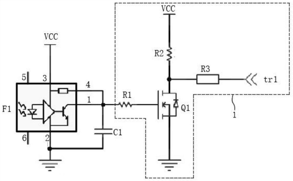
[0079] Such as figure 1 and figure 2 As shown, the signal acquisition module includes a fiber optic receiver F1 of model R2526 and a first conversion unit 1 . The first converting unit 1 includes a first field effect transistor Q1, a first resistor R1, a second resistor R2, and a third resistor R3. The output end of the optical fiber receiver F1 is connected to the gate of the first field effect transistor Q1, the drain of the first field effect transistor Q1 is connected to a 5V DC voltage through the second resistor R2, and the source of the first field effect transistor Q1 grounded. The drain of the first field effect transistor Q1 is also used as an output terminal and connected to the input terminal of the electrical signal processing module 2 through the third resistor R3, and the pin 1 of the optical fiber receiver F1 as the output terminal is connected to the first field effect transis...
Embodiment 3
[0085] On the basis of Embodiments 1 and 2, the first conversion unit 1, the optical fiber receiver F1, and the second electrical signal connector 8 in Embodiment 2 are removed, and the following components are added:
[0086] Signal generator 5, is used for outputting the signal that coincides with the trigger signal of beam laser 9;
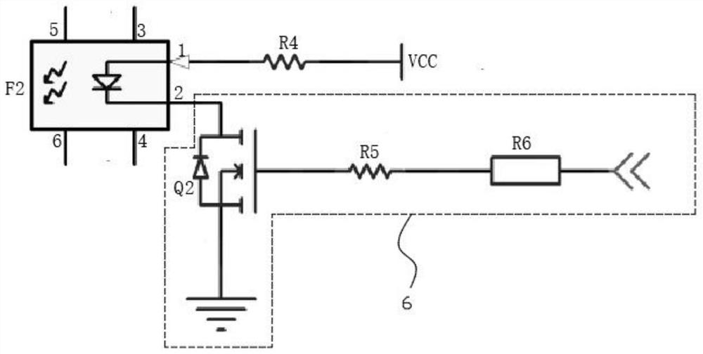
[0087] The second conversion unit 6 is used to output a potential different from the potential of the output terminal of the signal generator 5;
[0088] The fiber transmitter F2 is used to convert the potential output by the second conversion unit 6 into an optical signal, and the optical signal is transmitted to the beam laser 9 for triggering the beam laser 9 to generate seed light.
[0089] The first output end of the signal generator 5 is connected with the 555 timer F3 in the electrical signal processing module 2 as the input end pin 6 and the pin 2, and the second output end of the signal generator 5 is connected with the second conversi...
PUM
 Abstract
Description
Claims
Application Information
 - R&D
- Intellectual Property
- Life Sciences
- Materials
- Tech Scout
- Unparalleled Data Quality
- Higher Quality Content
- 60% Fewer Hallucinations
Browse by: Latest US Patents, China's latest patents, Technical Efficacy Thesaurus, Application Domain, Technology Topic, Popular Technical Reports.
© 2025 PatSnap. All rights reserved.Legal|Privacy policy|Modern Slavery Act Transparency Statement|Sitemap|About US| Contact US: help@patsnap.com


