
Forming process of pc composite material

A technology of composite materials and molding process, applied in the direction of coating, etc., can solve the problems of easy peeling off, weak adhesion between coating and plastic surface, increased cost, etc., and achieve the goal of improving bonding ability and scratch resistance Effect

Active Publication Date: 2021-12-14
NINGBO FUERDA SMARTECH CO LTD
View PDF5 Cites 0 Cited by
  • Summary
  • Abstract
  • Description
  • Claims
  • Application Information

AI Technical Summary

Problems solved by technology

[0004] In the field of automotive applications, most of them are automotive exterior decorations, such as windshields, exterior rearview mirrors, front bumpers, air intake grilles, anti-scratch strips, hub covers, etc. The disadvantage is that the surface of molded products has no scratch resistance. Poor, which greatly reduces the aesthetics of the product. At present, the improvement in this area mainly includes surface coating modification, modification by adding different fillers and additives, and blending modification with other polymers. Coating modification For example, chemical vapor deposition, vacuum deposition of diamond thin protective film, and sol-gel preparation of organic / inorganic hybrid coatings, among which chemical vapor deposition, vacuum deposition of diamond thin protective film, etc. are technically difficult and increase the cost. In terms of organic coatings prepared by the sol-gel method, direct coating is relatively simple and easy to implement, but the disadvantage is that the adhesion between the coating and the plastic surface is not strong, and there is a risk of easy peeling off. To solve this problem, there are Various enterprises and research institutes tend to improve the coating itself, and there are few applicable results, so it is necessary to find another way to improve

Method used


Image

  • Forming process of pc composite material
  • Forming process of pc composite material

Examples


preparation example Construction

[0022] For the preparation of composite nano-lubricant particles in this process, some existing technologies have been referred to, such as application publication number CN107814977, which is named as a kind of inorganic nano-lubricant for plastic processing and its preparation method. In the specific steps of preparing the inorganic lubricant, the addition of fluorine-containing carboxylic acid is abandoned in this scheme, and the content of halogen is reduced.

[0023] Specifically, the preparation of composite nano-lubricant particles, the steps are as follows:

[0024] In the first step, the aluminum sol is mixed with the inorganic nano-lubricant particles. As described in the above-mentioned patent documents, the aluminum sol is prepared by mixing aluminum alkoxide, alcohol, and water at a ratio of 1:23-45:55-100, for example, the ratio of the three Mix at a molar ratio of 1:25:60, or mix at a ratio of 1:30:60. The aluminum alkoxide is preferably aluminum isopropoxide. A...

Embodiment 1

[0044] During implementation, the molding process of PC composite materials includes the following steps

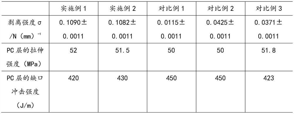
[0045] A. Add 0.6 parts of composite nano-lubricant to the material components of the above PC layer, mix and stir, and then place it in a twin-screw extruder to extrude the PC layer. The parameters of the twin-screw extruder are commonly used parameters.

[0046] B. Cover a thin layer of uniform water film on the PC layer formed in step A. The thickness of the water film is 50-60 μm, and a laser irradiation system is installed above the PC layer. The parameters of the nanosecond pulsed ultraviolet laser device: the energy density is 24-27J / cm 2 , the scanning speed is 1000-1100mm / s, the repetition frequency is 85kHz, and the scanning interval is 20μm. Under this parameter setting, the PC surface forms a groove-like morphology.

[0047] C. Coating the coating solution prepared by methyltrimethoxysilane, tetraethyl orthosilicate, and aluminum sol by gel method on the sur...

Embodiment 2

[0049] During implementation, the molding process of PC composite materials includes the following steps

[0050] A. Add 0.7 parts of composite nano-lubricant to the material components of the above PC layer, mix and stir, and then place it in a twin-screw extruder to extrude the PC layer. The parameters of the twin-screw extruder are commonly used parameters.

[0051] B. Cover a thin layer of uniform water film on the PC layer formed in step A, the thickness of the water film is 60-70 μm, install a laser irradiation system above the PC layer, nanosecond pulsed ultraviolet laser device parameters: energy density is 24-27J / cm 2 , the scanning speed is 800-1000mm / s, the repetition frequency is 60kHz, and the scanning interval is 20μm. Under this parameter setting, the PC surface forms a groove-like morphology.

[0052] C. Coating the coating solution prepared by methyltrimethoxysilane, tetraethyl orthosilicate, and aluminum sol by gel method on the surface of the modified PC l...


PUM

PropertyMeasurementUnit
particle diameteraaaaaaaaaa
thicknessaaaaaaaaaa
melt flow indexaaaaaaaaaa

Abstract

The invention discloses a molding process of a PC composite material, which comprises the following steps: A, adding a composite nano-lubricant prepared after drying aluminum sol mixed with inorganic nano-lubricant particles into the material components of the PC layer, and then forming the PC layer; B. The surface of the formed PC layer is modified by pulsed laser irradiation to increase the surface roughness; C. The coating solution is prepared by methyltrimethoxysilane, tetraethyl orthosilicate, and aluminum sol by gel method, and the coating solution is coated The surface of the modified PC layer in step B is dried to form a PC composite multilayer body. In this plan, the coating method is used to improve the scratch resistance of the PC material, and the aluminum sol is compounded with an inorganic nano-lubricant. According to the method of modifying the surface of the PC layer to improve the surface roughness, a coating with an organic-inorganic cross-linked network structure is formed through a co-condensation reaction. After testing, the coating has good adhesion to the PC surface, and the formed PC-coating is composite The multilayer body has strong scratch resistance and good heat resistance.

Description

technical field [0001] The invention relates to the technical field of polymer material preparation for vehicles, in particular to a molding process of PC composite materials. Background technique [0002] Plastics are increasingly replacing metals in the manufacture of auto parts, such as automotive exterior parts, due to their excellent processability, excellent performance, and cost reduction, especially weight reduction. [0003] Polycarbonate (PC) is a thermoplastic engineering plastic with excellent comprehensive performance developed in the 1950s. It is odorless, tasteless, non-toxic, rigid and tough. In addition, it has outstanding impact resistance, dimensional stability and other properties. Heat-resistant and cold-resistant properties, itself or composite materials are widely used in electronics, automobiles, aerospace, optical discs and other technical fields. [0004] In the field of automotive applications, most of them are automotive exterior decorations, suc...

Claims


Application Information

Patent Timeline
Patent Type & Authority Patents(China)
IPC IPC(8): C08J7/12C08J7/04C09D183/04C09D183/02C09D7/61C08L69/00C08L55/02C08K9/06C08K7/20C08K3/22
CPCC08J7/123C08J7/042C09D4/00C09D183/04C09D183/02C09D7/61C08L69/00C08G77/02C08G77/04C08J2369/00C08J2483/04C08J2483/02C08K2003/2227C08L55/02C08K9/06C08K7/20C08K3/22
Inventor 吴成华洪德腾
Owner NINGBO FUERDA SMARTECH CO LTD
Learn More