Composite evaluation equipment and method for aluminum alloy laser welding structure

A technology of laser welding and welding structure, applied in testing metal structure, testing metal, measuring device, etc., can solve the problems of serious softening of welded joints, large latent heat of fusion, inability to quantitatively test the performance of welded structures, etc., and achieve a high degree of automation , to achieve the effect of accurate evaluation

Active Publication Date: 2021-08-20
NANJING UNIV OF AERONAUTICS & ASTRONAUTICS
View PDF4 Cites 1 Cited by
  • Summary
  • Abstract
  • Description
  • Claims
  • Application Information

AI Technical Summary

Problems solved by technology

[0003] Among them, aluminum alloy is the main material used in aerospace, which has the advantages of light weight, good plasticity, good forming, corrosion resistance, and good processing performance. However, aluminum alloy has some disadvantages as a welding material, such as serious softening of aluminum alloy welded joints; thermal expansion coefficient Large, easy to produce welding deformation; high thermal conductivity and electrical conductivity, large specific heat capacity, latent heat of fusion, easy to produce defects such as incomplete penetration, incomplete fusion and pores
Residual stress, deformation and defects will seriously affect the strength, stiffness and performance of welded structural parts
[0004] At present, the detection methods for aluminum alloy welded structures mainly include five non-destructive testing technologies: radiographic testing, ultrasonic testing, penetration testing, magnetic particle testing and eddy current testing, but each non-destructive evaluation method has limitations and cannot be comprehensively, efficiently and quantitatively. Test out the performance of welded structures

Method used


Image

  • Composite evaluation equipment and method for aluminum alloy laser welding structure
  • Composite evaluation equipment and method for aluminum alloy laser welding structure

Examples


Embodiment Construction

[0041] In order to facilitate the understanding of those skilled in the art, the present invention will be further described in detail below in conjunction with the accompanying drawings and embodiments. It should be understood that the specific embodiments described here are only used to explain the present invention, but not to limit the present invention. In addition, it should be noted that, for the convenience of description, only some structures related to the present invention are shown in the drawings but not all structures.

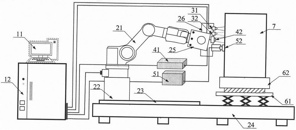
[0042] The invention discloses a composite evaluation equipment for aluminum alloy laser welding structure, which mainly includes a control system, a motion system, a welding seam location tracking system, a portable X-ray diffractometer, an ultrasonic detector, a detection work platform and an aluminum alloy laser welding structure pieces.

[0043] The present invention is further illustrated by a specific embodiment below.

[0044] This examp...


PUM


Abstract

The invention discloses composite evaluation equipment and method for an aluminum alloy laser welding structure. The equipment mainly comprises a control system, a movement system, a welding seam locating and tracking system, a portable X-ray diffractometer, an ultrasonic detector and a detection working platform. The invention aims to realize the detection and evaluation of the welding structure on the premise of not damaging the aluminum alloy welding structure. The welding seam locating and tracking system is used for carrying out recognition, positioning and three-dimensional shape reconstruction on a welding seam, and a specific quality detection means is selected according to the geometrical characteristics of a weldment. A six-axis robot carries the welding seam locating and tracking system, theportable X-ray diffractometer and the ultrasonic detector. Detection of the aluminum alloy laser welding structure is achieved, and detection data are collected and analyzed to obtain an evaluation result. A detection and evaluation means including welding seam locating and scanning, three-dimensional model reconstruction, parameter extraction, reasonable detection means selection, data statistical analysis and conclusion evaluation is formed.

Description

technical field [0001] The invention relates to the technical field of aluminum alloy structure evaluation, in particular to a composite evaluation equipment and method for aluminum alloy laser welding structure. Background technique [0002] Welding technology is a common metal connection method nowadays. Compared with other metal processing methods, it has the advantages of high structural strength, fast speed, short production cycle, small deformation of structural parts, simple equipment, material saving, and high airtightness of joints. To achieve reliable, accurate and efficient connection of materials, it is widely used in aerospace, construction, ships, vehicles, electronic equipment and other industries. In the field of aerospace, aluminum alloys, titanium alloys, etc. are the most widely used materials. The common welding methods are argon arc welding, laser welding, friction stir welding, etc., which can reduce the weight of the overall structure and improve the i...

Claims


Application Information

Patent Timeline
Patent Type & Authority Applications(China)
IPC IPC(8): G01N23/207G01N29/04G01N33/204G01N35/00
CPCG01N23/207G01N29/04G01N33/204G01N35/00584G01N35/0099G01N2291/0234
Inventor 赵艳秋占小红李悦
Owner NANJING UNIV OF AERONAUTICS & ASTRONAUTICS
Why Eureka
Try Eureka