Water flushing slag industrial waste gas treatment device

A technology for industrial waste gas and treatment equipment, which is applied in the direction of heating equipment, dispersed particle filtration, lighting and heating equipment, etc. It can solve the problems that waste gas cannot cool down liquid water, etc., and achieve the effect of heat transfer, dryness maintenance and efficiency improvement

Inactive Publication Date: 2021-11-05
南通卡森环境科技有限公司
View PDF3 Cites 1 Cited by
  • Summary
  • Abstract
  • Description
  • Claims
  • Application Information

AI Technical Summary

Problems solved by technology

[0005] Aiming at the deficiencies of the prior art, the present invention provides an industrial waste gas treatment device for washing slag with water, which solves the problem that the existing industrial waste gas treatment device cannot cool the waste gas well and reduce the liquid water content in the waste gas, and improves the The heat conduction efficiency of the device improves the heat utilization efficiency of the exhaust gas and ensures that the device can be used for a long time to remove liquid water in the exhaust gas

Method used


Image

  • Water flushing slag industrial waste gas treatment device
  • Water flushing slag industrial waste gas treatment device
  • Water flushing slag industrial waste gas treatment device

Examples


Embodiment 1

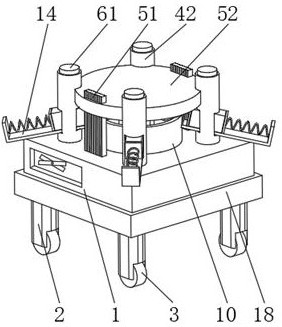
[0037] see Figure 1-7 , the present invention provides a technical solution: an industrial waste gas treatment device for water flushing slag, including a limit frame 1, a support leg 2 is symmetrically installed on the bottom of the limit frame 1, and a roller 3 is installed on the bottom of the support leg 2, and the position limit The external settings for box 1 are:

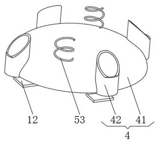
[0038] Cooling device 4, the cooling device 4 has a heat conduction plate 41, the top of the heat conduction plate 41 is symmetrically installed with a vent pipe 42, the vent pipe 42 runs through the heat conduction plate 41 and extends to the bottom of the heat conduction plate 41, and the top end of the vent pipe 42 runs through the limit frame 1 and extends to the top of the limit frame 1;

[0039] The heat conduction device 5, the heat conduction device 5 has a heat conduction plate 51, the top end of the heat conduction plate 51 extends to the top of the limit frame 1 and is equipped with a heat collec...

Embodiment 2

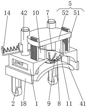
[0046] see Figure 1-7 , the present invention provides a technical solution: on the basis of Embodiment 1, a heat-conducting groove 7 is provided on the top of the limiting frame 1, and a heat-resistant film 8 is installed inside the heat-conducting groove 7, and the top of the heat-resistant film 8 is filled with water , the bottom of the heat-resistant film 8 is uniformly installed with a metal sheet 9 , and the metal sheet 9 penetrates the heat-resistant film 8 and extends to the outside of the heat-resistant film 8 .

[0047] The top of the limiting frame 1 is fixedly connected with a water retaining ring 10 near the position of the heat conduction groove 7, and both sides of the inner wall of the water retaining ring 10 are fixedly connected with a support frame 11, and the top of the support frame 11 is fixedly connected with the heat collecting plate 52.

[0048] One side of the air pipe 42 is fixedly connected with a track frame 14 , the track frame 14 runs through th...


PUM


Abstract

The invention discloses a water flushing slag industrial waste gas treatment device which comprises a limiting frame, supporting legs are symmetrically installed at the bottom of the limiting frame, rolling wheels are installed at the bottoms of the supporting legs, a cooling device is arranged outside the limiting frame, the cooling device is provided with a heat conduction disc, and ventilation pipes are symmetrically installed at the top of the heat conduction disc; a heat conduction device is arranged outside the limiting frame, the heat conduction device is provided with a heat conduction plate, and one end of the top of the heat conduction plate extends to the position above the limiting frame and is provided with a heat collection plate; an evaporation device is arranged outside the limiting frame, the evaporation device is provided with absorbent cotton, the absorbent cotton is fixedly connected with the ventilation pipe, and the invention relates to the technical field of industrial waste gas treatment. According to the water slag flushing industrial waste gas treatment device, the purposes of well cooling waste gas and reducing the content of liquid water in the waste gas are achieved, the heat conduction efficiency of the device is improved, the heat utilization efficiency of the waste gas is improved, and it can be guaranteed that the device is used for a long time to remove the liquid water in the waste gas.

Description

technical field [0001] The invention relates to the technical field of industrial waste gas treatment, in particular to an industrial waste gas treatment device for washing slag with water. Background technique [0002] At present, the treatment method of yellow phosphorus slag adopts the slag pool water quenching method, that is, to ensure a certain water level in the slag pool, and the molten slag flows directly into the slag pool through the slag ditch for water quenching. Methods A large amount of water vapor is produced when the phosphorus slag is quenched by water, and the water vapor contains a large amount of fluorine-containing and other toxic substances, which are directly discharged into the atmosphere and cause serious pollution. In addition, when the phosphorus slag is captured by driving, the site environment is bad, and the sewage and water vapor are discharged in an orderly manner. If it cannot be effectively managed, the water vapor will be very large after ...

Claims


Application Information

Patent Timeline
Patent Type & Authority Applications(China)
IPC IPC(8): B01D46/30B01D46/00B01D53/26F26B5/16F26B23/00F28D21/00
CPCY02P70/10
Inventor 张裕
Owner 南通卡森环境科技有限公司
Why Eureka
Try Eureka