Preparation method of defective nanofiber carbon carrier coupled iron monatomic catalyst

A nanofiber and carbon carrier technology, applied in the field of catalysis and new energy nanomaterials, can solve the problems of low CO2RR reaction activity and low specific surface area of ​​the catalyst, and achieve the effect of improving the catalytic performance.

Active Publication Date: 2022-02-11
UNIV OF ELECTRONICS SCI & TECH OF CHINA
View PDF4 Cites 2 Cited by
  • Summary
  • Abstract
  • Description
  • Claims
  • Application Information

AI Technical Summary

Problems solved by technology

[0004] The purpose of the present invention is to provide a method with simple process, low cost and green environmental protection to prepare a non-precious metal single-atom catalyst with high-efficiency CO2RR performance, and solve the problem of low CO2RR reactivity caused by the low specific surface area of ​​existing catalysts

Method used


Image

  • Preparation method of defective nanofiber carbon carrier coupled iron monatomic catalyst
  • Preparation method of defective nanofiber carbon carrier coupled iron monatomic catalyst
  • Preparation method of defective nanofiber carbon carrier coupled iron monatomic catalyst

Examples


Embodiment 1

[0054] The electrospinning method was used to prepare the iron single atom anchored in the nanofiber carbon support material.

[0055] Concrete preparation steps are as follows:

[0056] 1) Add 0.3 g of Fe-doped MOF into 3.55 mL of N,N-dimethylformamide, and stir ultrasonically to form a dispersion.

[0057] 2) Add 0.3 g of polyacrylonitrile into the above dispersion liquid, stir for 24 hours and ultrasonically homogenize.

[0058] 3) The above mixed solution was transferred to a needle tube for electrospinning, and the voltage between the positive and negative electrodes was selected as 17kV to obtain Fe-doped metal organic framework nanofibers coated with polyacrylonitrile.

[0059] 4) Pre-oxidize the above materials in a muffle furnace at 220° C. for 2 hours.

[0060] 5) The above materials were reacted at 900° C. for 2 h under the condition of Ar as protective gas.

[0061] 6) Mix the above materials in 1M HNO 3 The solution was washed once, and dried under vacuum at 8...

Embodiment 2

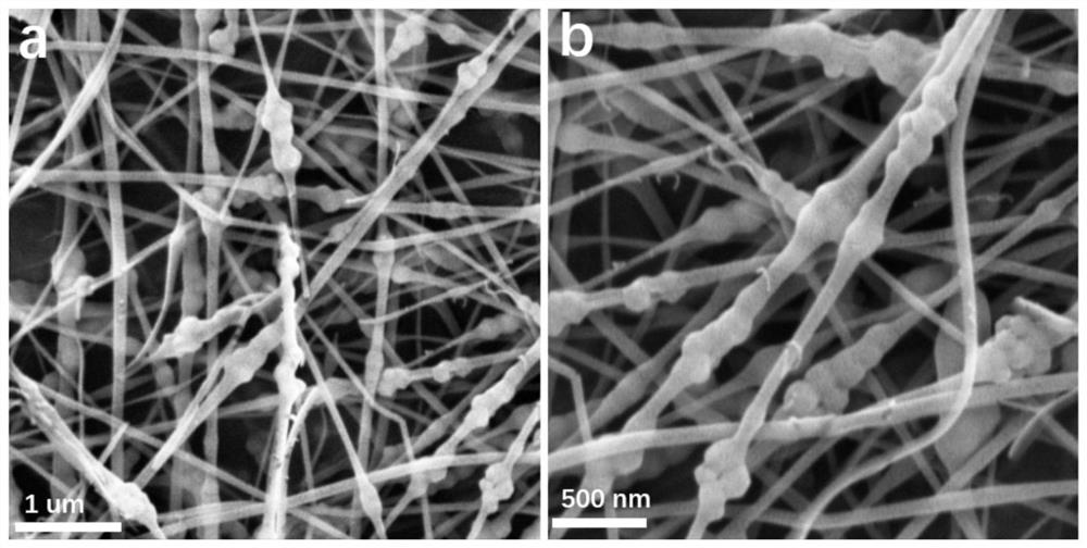
[0064] The steps in Example 2 are similar to those in Example 1, and the other reaction conditions remain unchanged, except that the amount of Fe-doped metal-organic framework in step 1) is changed to 0.5 g, and the amount of polyacrylonitrile in step 2) is changed to 0.25 g, and other reaction conditions remain unchanged. figure 2 The SEM image of the Fe-doped metal-organic framework nanofibers coated with polyacrylonitrile was obtained for Example 2, as can be seen from the figure figure 1 The homogeneously coated nanofibers are no longer seen, indicating that the amount of metal-organic framework and polyacrylonitrile added has a great influence on the prepared fiber structure.

Embodiment 3

[0066] The steps in Example 3 are similar to those in Example 1, and other reaction conditions remain unchanged, except that the heat treatment temperature in step 7) is changed to 900°C. Figure 9 Obtain the linear cyclic voltammogram (LSV) of sample under argon and carbon dioxide gas saturation for embodiment 3, electrolyte is the KHCO of 0.5M 3 solution, the scan window is 0 to -1V (vs. RHE), and the scan speed is 5mV / s. compared to Figure 8 It can be seen that, compared with the LSV curve of the sample treated at 1100 °C, the LSV curve obtained by the second heat treatment at 900 °C is lower in current density, indicating that the temperature of the second heat treatment has a great influence on the activity of the catalyst.

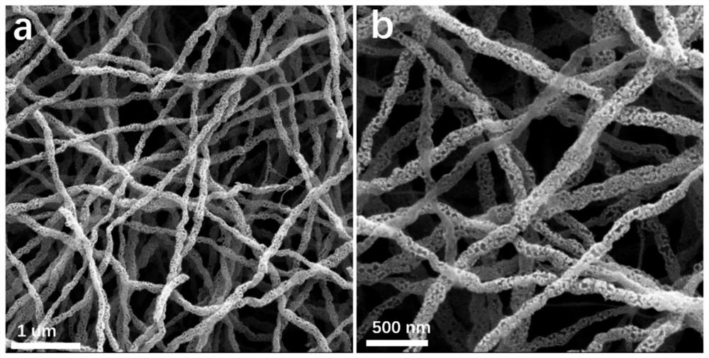
[0067] The morphology of the obtained carbon support-coupled iron single-atom catalyst nanofibers with defects was characterized by scanning electron microscopy.

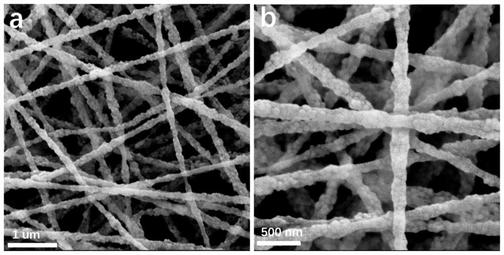
[0068] figure 1 It is the SEM image of the polyacrylonitrile-coated Fe-doped metal...


PUM

PropertyMeasurementUnit
diameteraaaaaaaaaa
concentrationaaaaaaaaaa

Abstract

The invention relates to a preparation method of a defective nanofiber carbon carrier coupled iron monatomic catalyst, and belongs to the field of new energy nanomaterials and the technical field of catalysis. The invention aims to solve the problem of low CO2RR reaction activity caused by low specific surface area of the existing catalyst. According to the main scheme, a one-dimensional nanofiber material is prepared from a Fe-doped metal organic framework, polyacrylonitrile and N, N-dimethylformamide through an electrostatic spinning reaction, then Fe single atoms are prepared through high-temperature heat treatment under the protective atmosphere and are loaded on a nitrogen-doped carbon carrier, then under the assistance of diaminonitrile, unstable pyridine nitrogen and pyrrole nitrogen in a carbon skeleton are removed through secondary heat treatment at the temperature of 1,100 DEG C, the carbon-carrier-loaded Fe monatomic catalyst with the intrinsic defects is obtained, and the prepared carbon-carrier-loaded Fe monatomic nanofiber material with the intrinsic defects has high catalytic activity and stability and can be applied to an electrode material for electrocatalytic CO2 reduction reaction.

Description

technical field [0001] The invention relates to a preparation method of a defect nanofiber carbon carrier coupled iron single atom catalyst, which belongs to the field of new energy nanomaterials and the field of catalysis technology. Background technique [0002] Currently, CO 2 The excessive emission of greenhouse gases such as global warming and the sharp decline in biodiversity are increasingly serious environmental problems, which are increasingly threatening the sustainable development of human beings. At present, scientists use a variety of reduction techniques to reduce CO 2 Conversion into chemicals or energy, including photoelectrochemical reduction, biochemical reduction, thermochemical reduction, and electrochemical reduction. However, the photochemical reduction efficiency is low, the biological reduction stability is poor, the thermal reduction conversion efficiency is low, and the energy consumption is large. By electrochemical reduction (CO 2 reduction r...

Claims


Application Information

Patent Timeline
Patent Type & Authority Applications(China)
IPC IPC(8): C25B11/054C25B11/065C25B11/075C25B11/031C25B3/26C25B3/07C25B3/03C25B1/23
CPCC25B11/054C25B11/065C25B11/075C25B11/031C25B3/26C25B3/07C25B3/03C25B1/23
Inventor 吴睿李昭陈俊松赵磊王俊杰李平波
Owner UNIV OF ELECTRONICS SCI & TECH OF CHINA
Why Eureka
Try Eureka