High-conductivity electrolyte aqueous solution electroinjection system and method

A technology with high conductivity and electrolyte, applied in circuits, discharge tubes, electrical components, etc., can solve problems such as poor working effect, high cost, and difficulty in adjusting conductivity, and achieve low cost of working medium, low vapor pressure, and high performance stable effect

Pending Publication Date: 2022-03-01
BEIHANG UNIV
View PDF0 Cites 0 Cited by
  • Summary
  • Abstract
  • Description
  • Claims
  • Application Information

AI Technical Summary

Problems solved by technology

Early electrospray thrusters used electrolyte solution as a working medium. The solvent of the electrolyte solution was an organic solvent, which could achieve high conductivity, but there were volatility problems in vacuum and solute precipitation problems that made the work effect not good. Therefore, this field Electrolyte solutions are generally considered unsuitable as working fluids for electrospray thrusters
In addition, ionic liquids are currently used as working fluids for electrospray thrusters. However, compared with aqueous electrolyte solutions, the use of ionic liquids will result in higher costs and it is difficult to adjust the conductivity.

Method used


Image

  • High-conductivity electrolyte aqueous solution electroinjection system and method
  • High-conductivity electrolyte aqueous solution electroinjection system and method
  • High-conductivity electrolyte aqueous solution electroinjection system and method

Examples


Embodiment Construction

[0035] Exemplary embodiments of the present disclosure will be described in more detail below with reference to the accompanying drawings. Although exemplary embodiments of the present disclosure are shown in the drawings, it should be understood that the present disclosure may be embodied in various forms and should not be limited by the embodiments set forth herein. Rather, these embodiments are provided for more thorough understanding of the present disclosure and to fully convey the scope of the present disclosure to those skilled in the art. It should be noted that, unless otherwise specified, the technical terms or scientific terms used in the present invention shall have the usual meanings understood by those skilled in the art to which the present invention belongs.

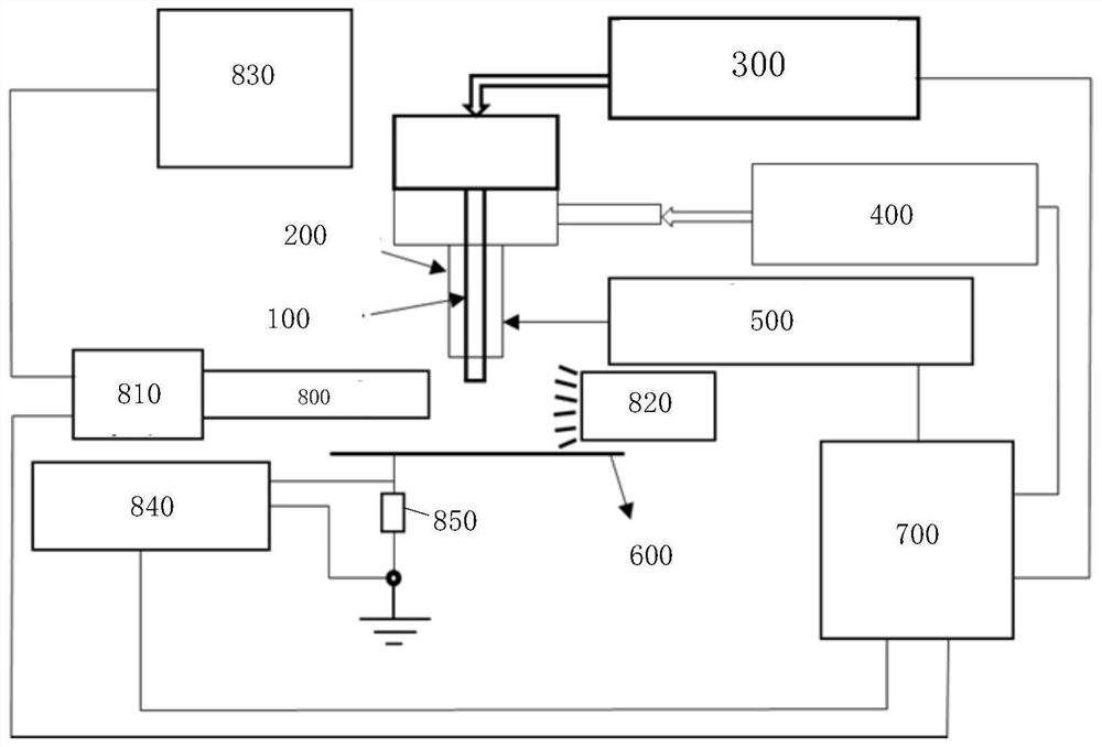
[0036] The following references are attached Figure 2-4 , a high-conductivity electrolyte aqueous solution electrospray system provided according to an embodiment of the present invention is described i...


PUM

PropertyMeasurementUnit
Outer diameteraaaaaaaaaa
The inside diameter ofaaaaaaaaaa
Outer diameteraaaaaaaaaa

Abstract

A high conductivity electrolyte aqueous solution electroinjection system and method, comprising: an inner capillary tube and an outer capillary tube arranged coaxially, the inner capillary tube extending a length from the outer capillary tube; the inner capillary tube injection pump is used for conveying an electrolyte aqueous solution to the inner capillary tube; the outer capillary tube injection pump is used for conveying ionic liquid to the outer capillary tube; the high-voltage power supply is used for loading high potential on the inner capillary tube and the outer capillary tube; the current collecting plate is spaced from the extending tail end of the inner capillary tube by a certain distance and is grounded, so that a strong electric field is formed between the current collecting plate and the inner capillary tube as well as the outer capillary tube; and the central control system is operably connected with the above parts and controls the parts.

Description

technical field [0001] The invention belongs to the technical field of electrospray ion sources, and in particular relates to an electrospray system and method using a coaxial capillary for a high-conductivity electrolyte aqueous solution. Background technique [0002] The application of electrospray phenomenon is very extensive, and can be used in mass spectrometry, electrospinning, electrostatic inkjet, the manufacture of microsphere particles and films with controllable nanostructures, and electrospray thrusters. When the electrospray phenomenon is applied, the fluid droplets form a cone shape under a strong electric field, that is, the Taylor cone. The Taylor cone will only form after the applied electric field exceeds a certain critical value, and its cone half angle is generally 49.3°. When the applied electric field is strong enough , a cone jet is emitted from the tip of the Taylor cone. [0003] Electrospray can be used as an ion source in mass spectrometry, and it...

Claims


Application Information

Patent Timeline
IPC IPC(8): F03H1/00H01J49/16
CPCF03H1/0087H01J49/165
Inventor 王伟宗程玉峰张金瑞刘昱涵刘伟李亦非王海波
Owner BEIHANG UNIV
Why Eureka
Try Eureka