System and method for coupling optical fiber image transmitting element with photosensitive surface in image sensor

An image sensor and optical fiber image transmission technology, which is applied in electrical components, image communication, components of TV systems, etc., can solve the problems of high coupling cost, easy occurrence of micro-displacement, and difficult monitoring of coupling effect, so as to avoid surface pollution. Effect

Pending Publication Date: 2022-03-08
CHINA BUILDING MATERIALS ACAD
View PDF0 Cites 2 Cited by
  • Summary
  • Abstract
  • Description
  • Claims
  • Application Information

AI Technical Summary

Problems solved by technology

[0003] At present, there is still no unified method and device for the coupling of the image intensifier and the CCD or CMOS camera. The coupling is a combination of mechanical or manual movement and microscope observation. The coupling accuracy is not high. Before the coupling is solidified, the optical fiber image transmission The component and CCD or CMOS camera are not easy to fix and prone to micro-displacement. In addition, the force on the coupling interface is not easy to control. When the force on the photosensitive surface is too large, it may even cause damage to the photosensitive surface of the chip.
The most critical thing is that the coupling effect is difficult to monitor during the coupling process, which makes the coupling somewhat random and uncontrollable, and the coupling pass rate is low, resulting in high coupling costs.
Another difficulty in coupling is how to remove the glass cover without damaging the photosensitive surface

Method used


Image

  • System and method for coupling optical fiber image transmitting element with photosensitive surface in image sensor
  • System and method for coupling optical fiber image transmitting element with photosensitive surface in image sensor
  • System and method for coupling optical fiber image transmitting element with photosensitive surface in image sensor

Examples


Embodiment 1

[0100] The coupled sample is a fiber optic cone and a CCD camera.

[0101] The fiber optic cone specifications are: diameter of the big end is 49mm, effective diameter is 44.6mm; diameter of the small end is 20×11mm, effective size is 19.5×10.8mm, magnification ratio is 2:1, and the diameter of the elemental filament is 6μm (big end).

[0102] The photosensitive surface of the CCD camera is 19.5×10.8mm, and the pixel size is 10×10μm.

[0103] The photosensitive surface of the chip is at the lower part of the output surface of the optical fiber cone.

[0104] Coupling Photosensitive Adhesive: Refractive Index n D 1.55; colorless and transparent; bonding strength >90Kg / cm 2 ;Visible transmittance>90%.

[0105] Light curing wavelength: ~320nm; Light curing time: 5-10s;

[0106] The system for coupling the optical fiber image transmission element and the photosensitive surface in the image sensor of this embodiment includes:

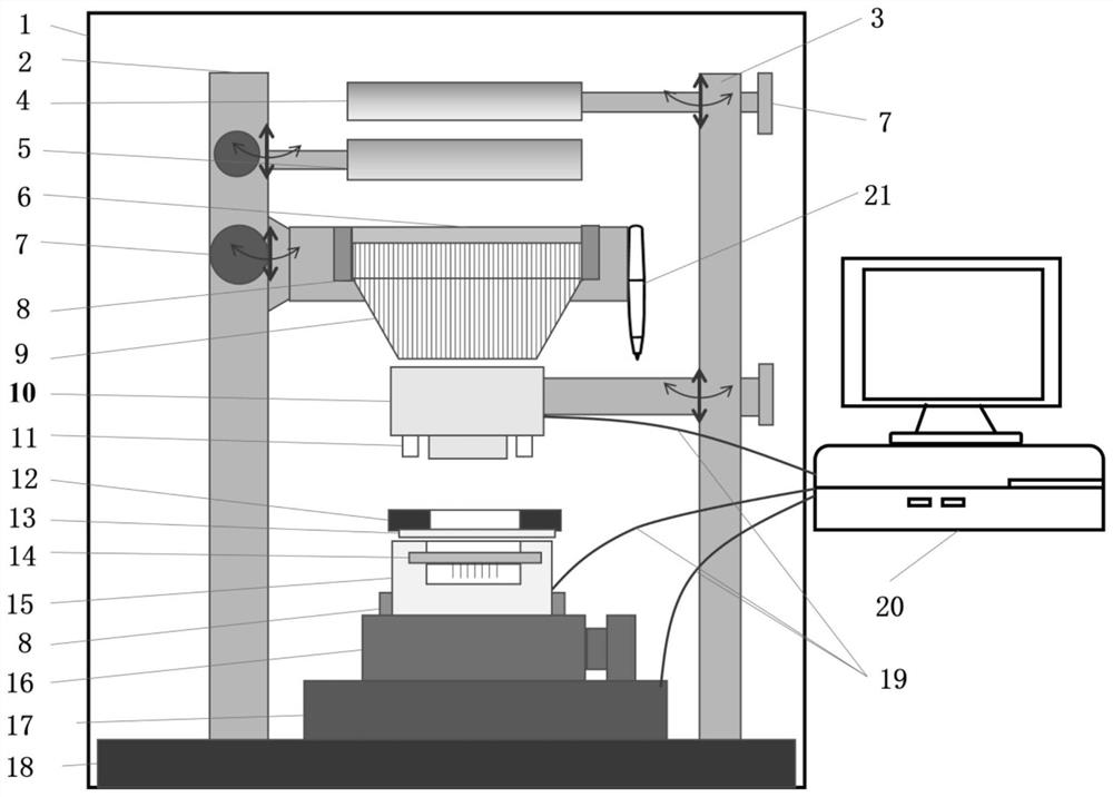
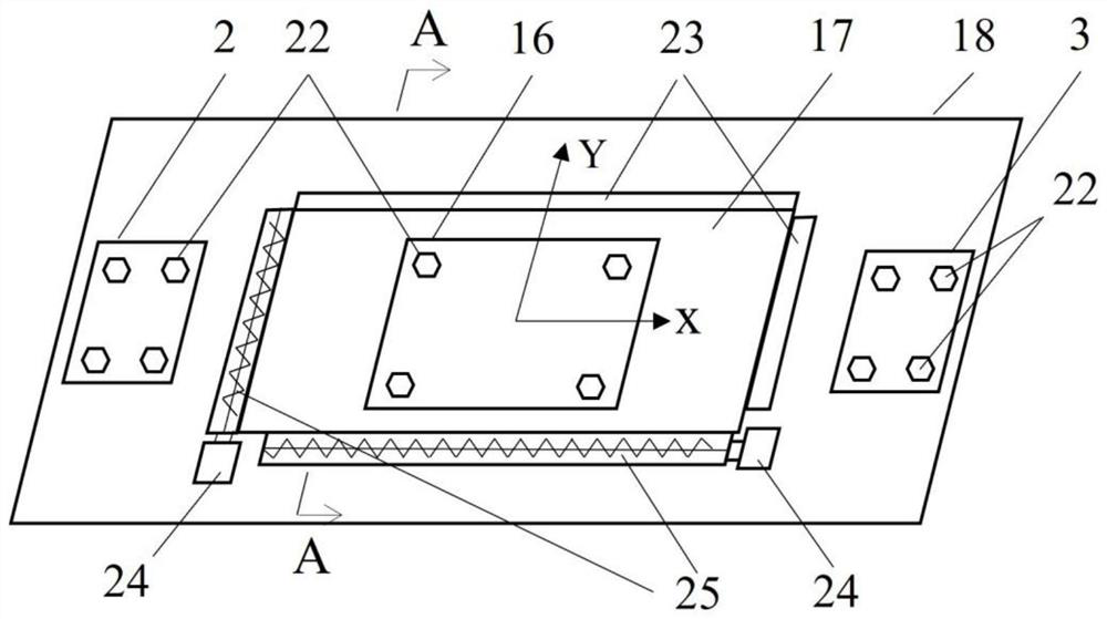
[0107] The main structure unit comprises a shadin...

Embodiment 2

[0122] Couple the sample to a fiber optic panel and a CMOS camera.

[0123] The specifications of the fiber optic panel are: outer diameter 21.85mm, effective diameter 18.3mm; unit wire diameter 6μm.

[0124] The pixel size of the CMOS camera chip is 5.5×5.5μm, and the area size of the photosensitive surface is 12.7×9.6mm.

[0125] The photosensitive surface of the chip is inside the light-transmitting surface of the fiber optic panel.

[0126] Coupling Photosensitive Adhesive: Refractive Index n D 1.7; 500-550nm average light transmittance > 98%; bonding strength > 70Kg / cm 2 ;

[0127] Light curing wavelength and time: UV wavelength 320-390nm, curing time: 20-30s;

[0128] The setting and positional relationship of each part of the system are the same as in Embodiment 1.

[0129] Through the above system, not only can the coupling quality be judged in real time, but also the characteristic performance indicators of the whole system can be measured:

[0130] Resolution a...

Embodiment 3

[0138]The coupled samples are an image inverter and a CMOS camera.

[0139] The specifications of the fiber optic inverter are: outer diameter 19mm, effective diameter 16.3mm. Limited by the size of the CMOS chip, the output end of the image inverter is processed into an annular surface of 16×14 mm, and the diameter of the unit wire is 6 μm. Inversion angle: 180°±1°;

[0140] The photosensitive surface of the chip is inside the light-transmitting surface of the fiber optic panel.

[0141] Coupling Photosensitive Adhesive: Refractive Index n D 1.7; 500-550nm average light transmittance > 98%; bonding strength > 70Kg / cm 2 ;

[0142] Light curing wavelength and time: UV wavelength 320-390nm, curing time: 5-10s;

[0143] Except the CMOS camera, all the other are the same as embodiment 1 in the described system. The CMOS camera uses a scientific grade CMOS chip with a pixel size of 6.5×6.5μm, a photosensitive surface area size of 16.6×14.0mm, and 5.5 million pixels.

[0144]...


PUM

PropertyMeasurementUnit
diameteraaaaaaaaaa
diameteraaaaaaaaaa
diameteraaaaaaaaaa

Abstract

The invention relates to a system and a method for coupling an optical fiber image transmitting element with a photosensitive surface in an image sensor. The system comprises a main body structure unit which comprises a light shield, a left support, a right support and a base, wherein the left support and the right support are arranged in the light shield; the displacement positioning unit comprises a CMOS (Complementary Metal Oxide Semiconductor) camera, a 360-degree rotating platform and an X/Y-direction displacement platform; the positioning heating unit comprises a temperature control meter, a heating device and a vacuum adsorption device which are arranged outside the main body structure unit; the optical fiber image transmitting element clamping unit comprises a gas-driven self-centering clamping device, a resolution/shearing standard template and a coupling interface pressure sensor; the monitoring display unit comprises a computer and a data line; the light source unit comprises an LED white light source, an ultraviolet light source and a light source controller. According to the system and the method provided by the invention, rapid optical curing coupling of the optical fiber image transmission element and the photosensitive surface in the image sensor can be realized, and the coupling effect can be evaluated in real time by detecting indexes such as coupling resolution and relative transmittance.

Description

technical field [0001] The invention belongs to the field of low-light night vision and particle detection imaging, and in particular relates to a system and method for coupling an optical fiber image transmission element with a photosensitive surface in an image sensor. Background technique [0002] Fiber optic image transmission materials mainly include hard fiber optic products such as fiber optic cones, fiber optic panels, and fiber optic image inverters. This type of material is the main window component in devices such as low-light night vision and particle detection, and also the key coupling medium component in ICCD or ICMOS image enhancement sensor devices. It is widely used in low-light night vision devices, framing / stripe cameras, ultraviolet / high energy ray / single photon detection and other devices. In order to digitize the image detected by the detection, it is necessary to digitally convert the surface image formed by the optical fiber image transmission eleme...

Claims


Application Information

Patent Timeline
Patent Type & Authority Applications(China)
IPC IPC(8): H04N5/225H04N5/232H04N5/372H04N5/374G01D21/02
CPCG01D21/02H04N23/50H04N23/56H04N23/55H04N23/695H04N25/71H04N25/76
Inventor 黄永刚焦朋赵冉王云付杨周游王久旺独雅婕
Owner CHINA BUILDING MATERIALS ACAD
Why Eureka
Try Eureka