Device and method for deacidifying flue gas of hazardous waste incineration system

A flue gas and deacidification technology, applied in chemical instruments and methods, separation methods, gas treatment, etc., can solve the problems of increased carbon emissions, unfavorable control costs, and high prices of baking soda, and achieve good control, improve utilization, Achieving zero emissions

Pending Publication Date: 2022-06-03
青岛海湾新材料科技有限公司
View PDF9 Cites 0 Cited by
  • Summary
  • Abstract
  • Description
  • Claims
  • Application Information

AI Technical Summary

Problems solved by technology

The disadvantage of this process is that the price of baking soda used in deacidification is relatively high, which is not conducive to the cost control of enterprises. After the reaction of baking soda and acid, a large amount of carbon dioxide will be generated, which will significantly increase the carbon emissions of the entire incineration system.

Method used


Image

  • Device and method for deacidifying flue gas of hazardous waste incineration system
  • Device and method for deacidifying flue gas of hazardous waste incineration system

Examples


Embodiment 1

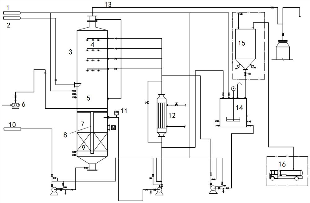
[0062] A hazardous waste incineration production line, the flue gas volume under working conditions is 66832-68661Nm 3 / h, the flue gas outlet temperature of the quench tower is 490-510°C, the inlet flue gas temperature of the deacidification tower is 150-180°C, and the sulfur dioxide concentration is 4500-6600 mg / Nm 3 , hydrogen chloride concentration 2000-3500mg / Nm 3 , the concentration of hydrogen fluoride is less than 100mg / Nm 3 , use the method in the present invention to carry out flue gas deacidification, with figure 1 For the deacidification device, a two-stage deacidification tower is used for absorption.

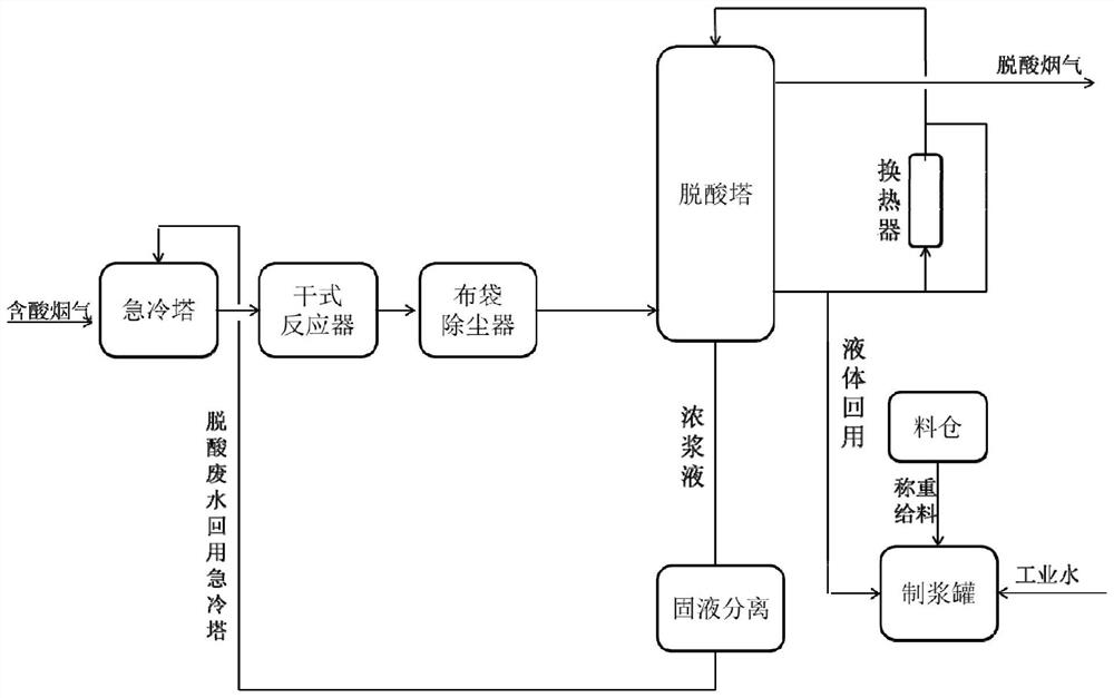
[0063] like figure 2 As shown, pulping was carried out according to the ratio of magnesium oxide to water as 1:5, and the dosage of magnesium oxide was 200kg / h. The obtained slurry is sent to the primary and secondary deacidification towers by the slurry pump, and the liquid-gas ratio is controlled at about 9. After aeration and solid-liquid separation, the l...

Embodiment 2

[0066] A medical waste incineration production line, the working condition flue gas volume is 8000-12000Nm 3 / h, the flue gas outlet temperature of the quench tower is 500-520°C, the inlet flue gas temperature of the acid absorption tower is 150-180°C, and the hydrogen chloride concentration is 3900-4700 mg / Nm 3 , the sulfur dioxide concentration is less than 50mg / Nm 3 , the concentration of hydrogen fluoride is less than 100mg / Nm 3 , use the method in the present invention to carry out flue gas deacidification, with figure 1 For the deacidification device, a single-stage deacidification tower is used for absorption.

[0067] like figure 2 As shown, pulping was carried out according to the ratio of magnesia to water as 1:6, and the dosage of magnesia was 50kg / h. The obtained slurry is sent to the single-stage deacidification tower respectively by the slurry centrifugal pump, and the liquid-gas ratio is controlled at about 10. After the liquid after absorbing acid gas is ...


PUM

PropertyMeasurementUnit
particle sizeaaaaaaaaaa

Abstract

The invention relates to a device and a method for deacidifying flue gas of a hazardous waste incineration system. Comprising a deacidification tower and a quench tower, a spraying structure is arranged on the upper portion in the deacidification tower, a solid-liquid separation area is arranged on the lower portion of the deacidification tower, a flue gas inlet is formed in the middle of the deacidification tower, an aeration area is arranged below the flue gas inlet in the deacidification tower and above the solid-liquid separation area, and a flue gas outlet is formed in the top of the deacidification tower. And thick slurry obtained in the solid-liquid separation zone is introduced into a quench tower. A deacidification tower is utilized, a circulating deacidification method is adopted, the technologies of spraying deacidification, aeration, solid-liquid separation and the like are integrated, and a heat exchange technology is added. According to the technology, the good deacidification effect can be guaranteed, the dosage of the deacidification agent can be well controlled, and the utilization rate of the deacidification agent is increased.

Description

technical field [0001] The invention belongs to the technical field of hazardous waste disposal, and in particular relates to a device and method for deacidifying flue gas of a hazardous waste incineration system. Background technique [0002] The information disclosed in this Background section is only for enhancement of understanding of the general background of the invention and should not necessarily be taken as an acknowledgement or any form of suggestion that this information forms the prior art already known to a person of ordinary skill in the art. [0003] The source and composition of hazardous waste recovered by hazardous waste disposal enterprises are very complex, and usually contain a large amount of chemical elements such as chlorine, sulfur, fluorine, nitrogen, and phosphorus. These chemical elements will produce a large amount of various acid gases such as hydrogen chloride, sulfur dioxide, hydrogen fluoride, nitrogen oxides, and phosphides during high-tempe...

Claims


Application Information

Patent Timeline
Patent Type & Authority Applications(China)
IPC IPC(8): B01D53/80B01D53/50B01D53/68
CPCB01D53/80B01D53/502B01D53/504B01D53/68B01D2251/402B01D2251/602B01D2257/2045B01D2257/2047B01D2258/0291Y02E20/30
Inventor 陈会来张学利伊盛鑫杨焕丽李成好李涛
Owner 青岛海湾新材料科技有限公司
Why Eureka
Try Eureka