

Nano particle surface physicochemical structure cutting and coating method
A nanoparticle, physical and chemical technology, applied in the field of cutting and coating the physical and chemical structure of the nanoparticle surface, can solve problems such as easy to produce agglomeration, and achieve the effects of less environmental pollution, overcoming repeated solvent separation, and simple coating process.
- Summary
- Abstract
- Description
- Claims
- Application Information
AI Technical Summary
Problems solved by technology
Method used
Image

Examples
Embodiment 1
[0039] Example 1 Nanoparticle TiO 2 Uniform coating by plasma polymerization
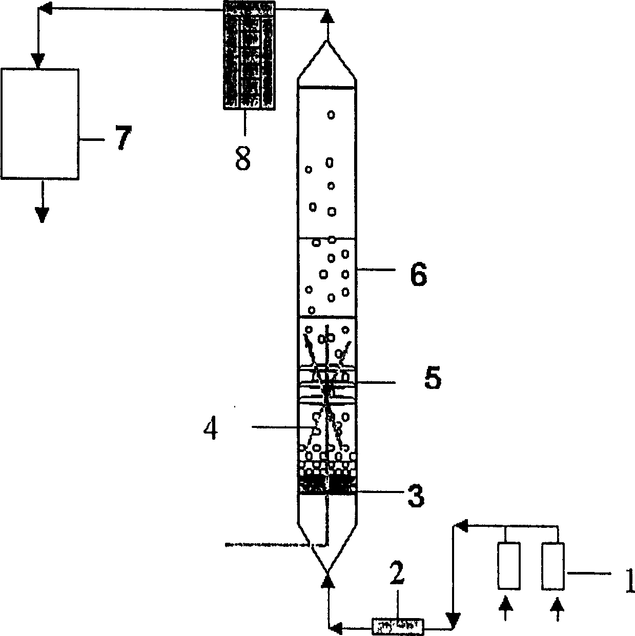
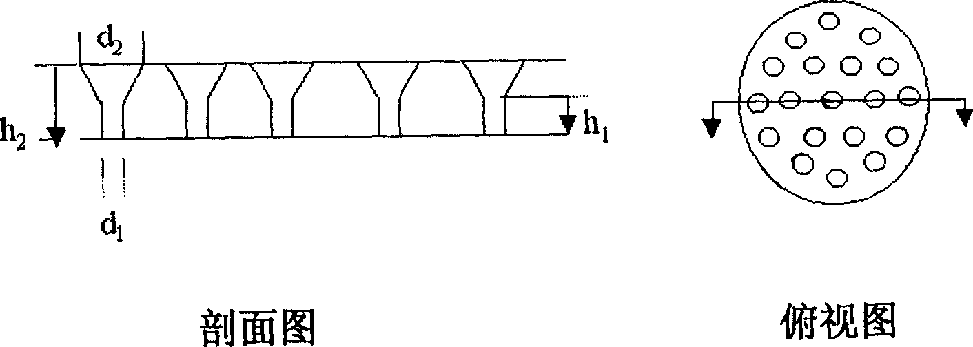
[0040] use figure 1 The plasma coating reactor setup shown was used for coating experiments. First, the TiO nanoparticles to be coated, with an average particle diameter of about 30nm, are pre-acted by a 50KV high-voltage electrostatic generator for 5 minutes to make it charged. After taking it out, immediately put it into the porous distribution plate 3 at the bottom of the plasma reactor 6 (for detailed structure, refer to figure 2 )superior. The reactor 6 is evacuated by the vacuum system 7 to a background vacuum of 5Pa. The monomeric acrylic acid and the carrier gas argon are respectively measured through the flow meter 1, and the volume ratio is 1:50. After being uniformly mixed in the gas mixer 2, they are introduced into the plasma reactor 6 at a flow rate of 10 sccm through the porous distribution plate 3 , so that the particles are in a fluidized state, and the vacuum degree drops to 1...
Embodiment 2
[0042] Example 2 Cr 2 o 3 Experiments on Effects of Nanoparticle Plasma Coating Conditions on Coating Thickness
[0043] use figure 1 For the plasma coating reactor device shown, the operation steps refer to Example 1.
[0044] in Cr 2 o 3 Nanoparticles are the coating objects, with an average particle size of 150nm, charged by a 20KV high-voltage electrostatic generator for 1 minute, immediately placed in the plasma reactor 6, vacuumed to a background vacuum of 4Pa, and injected with hexamethyl di A mixed gas of siloxane and nitrogen, the volume ratio of the two gases is 10:50, the flow rate is 60 sccm, and the vacuum degree is reduced to 200 Pa. Turn on the plasma generator 5 and the stirrer 4, control the discharge power to be 40W, the discharge time to be 8 hours, the discharge pulse ratio to be 50%, the pulse "on" time to be 2ms, and the stirring speed to be 500 rpm.
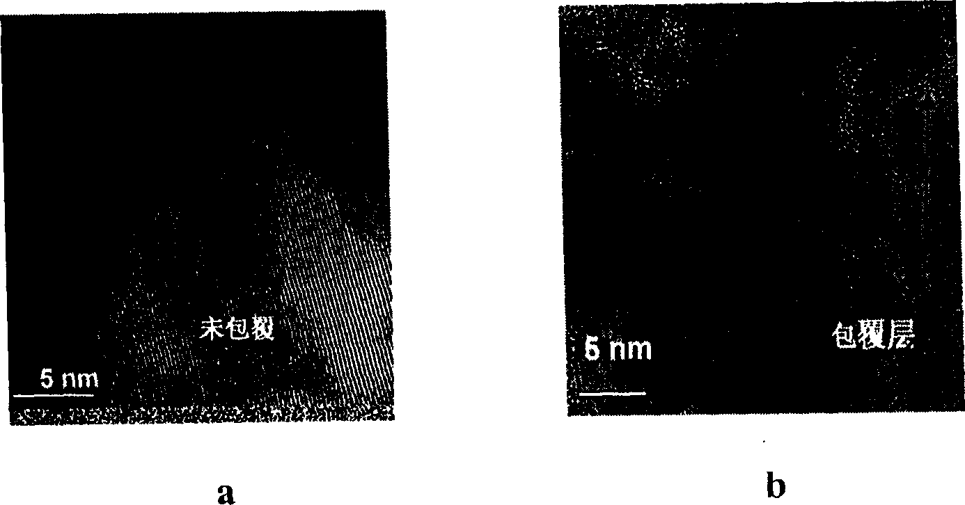
[0045] After coating, the sample was detected by high-resolution transmission electron microscopy ...
Embodiment 3
[0046] Example 3 The test of the influence of pulsating radio frequency plasma coating conditions on the surface roughness of the coating film
[0047] use figure 1 The plasma cladding reactor setup is shown.
[0048] In order to observe the relationship between the pulsating radio frequency plasma coating conditions and the surface roughness of the coating film, a flat glass sheet is selected as the coating object. After cleaning, it is placed in the plasma reactor 6 and vacuumed to a background vacuum of 4Pa. , into a mixed gas of hexamethyldisiloxane and argon, the volume ratio of the two gases is 10:90, the flow rate is 10 sccm, and the vacuum is reduced to 30 Pa. Turn on the plasma generator 5 for discharge polymerization. Discharge time is 1 hour, polymerization finishes, takes out sample and does atomic force microscope (AFM) analysis, the atomic force microscope picture of gained sample is shown in Figure 6 . Figure 6 The discharge power of medium a is 3w, the pu...
PUM
 Abstract
Description
Claims
Application Information